![]()
The square root of three.
This is one of the top 5 most misunderstood and asked about topics in three phase power. Why and where do we use the square root of three (1.73) in our formulas when solving questions for the Electrical PE Exam, and just where exactly does it come from?
Having a solid foundation on where it comes from helps to have a much more intuitive understanding of three phase power circuits and ensures that it is used properly.
We see the square root of three all the time in three phase formulas.
Most notably when converting the magnitude of phase voltage to line to line voltage for a wye system:
![]()
When converting the magnitude of phase current to line to line current for a delta system:
![]()
And when finding the magnitude of three phase apparent power:
![]()
Is it necessary to understand where the square root of three comes from for electrical three phase formulas in order to successfully pass the Electrical PE Exam?
Of course not.
However, understanding where the square root of three comes from is a sure fire way to eliminate mistakes in your work from using it incorrectly and increasing your chance at earning your highest score possible on the Electrical PE Exam.
In the most simplest terms, the square root three is a magnitude multiplier that accompanies a 30 degree phase shift between line voltages and their respective phase voltages for a wye system, and line currents and their respective phase currents for a delta system that is a result of adding (or subtracting) two vectors that are equal in magnitude and 120 degrees apart.
The key of course is to prevent getting questions wrong on the Electrical PE Exam not because your math is incorrect, but because you applied the wrong formula at the wrong time.
Or because you either used the square root of three when you shouldn’t have, or forgot to use it when you were meant to.
Let’s take a look at the math that goes on under the hood to see where it comes from.
Or you may also skip and just watch the video demonstration:
Video Demonstration: Wye Circuits- Square Root Three
Wye Circuits- Square root three, Line Voltage, Phase Voltage, and the 30 degree Phase Shift
For a balanced, positive, ABC sequence wye system we will have the following phase voltage vectors when the A phase to neutral voltage is at zero degrees:
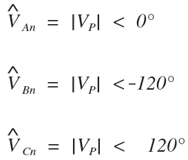
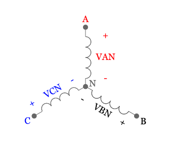
Where the phasor diagram for the phase voltages looks like this:
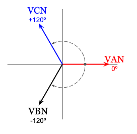
Now to get to line voltage, we have to measure the voltage across two lines, skipping the neutral. If we measured the A line voltage, which is the same as the voltage across A line and B line, it would look something like this:
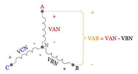
To get to the correct formula for the A line voltage, we have to add the voltages from A to neutral, and from neutral to B. Play close attention to the polarity in the diagram and notice how we are actually subtracting the two phase voltages:

Next lets start the long process of converting both to rectangular (since we can’t add in polar), then subtract the two vectors, and lastly convert to polar and see what we end up with for our A line voltage
First a quick trig and geometry refresher on how to convert between polar and rectangular:
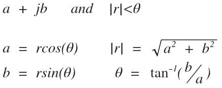
Okay lets begin.
I recommend getting a paper and pen and following along to make sense of the math:

That is the value of the line voltage in rectangular form, let’s covert to polar form and see what happens:

This means that the Line to Line voltage of a balanced system, will always be equal to:
The difference of two phase voltages (because of polarity when crossing the neutral)
Which equals the square root three times the phase voltage magnitude
and will lead the phase voltage by an angle of 30 degrees
The phasor diagram looks like this:
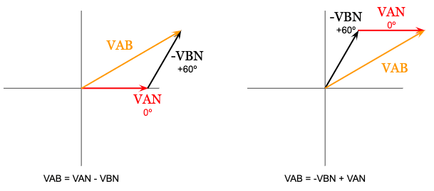
Beautiful.
The same math works out for delta systems since for a balanced system the phase currents are also equal in magnitude and are spaced 120 degrees apart.
Try doing the math for a delta system on your own
By adding two phase currents to get one line current:
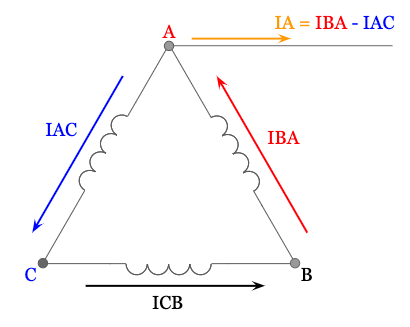
And see if you arrive at:

Or, you can skip ahead and watch the below video where I work it out for you:
Video Demonstration: Delta Circuits – Square Root Three
Bonus
What about Apparent Power?
So the last part to address after covering where the square root three comes from for wye and delta circuits
is where the square root three comes from when solving for the magnitude of three phase apparent power:
![]()
First we need to remember that three phase power, is really just three times the power that is being consumed or delivered in each individual phase:

Lets expand this and plug in the phase values:

For this example we are just going to look at the magnitude of apparent power, so we will use only the magnitudes and drop the conjugate:
(and if you did need the angle, you could always find it from the inverse cosine of the power factor)
![]()
Next let’s match the original three phase formula that uses line values, by substituting line values for the phase values.
This works either way for a wye or delta system:
If it’s a wye system, phase current equals line current, but we know the phase voltage is √3 times smaller than line voltage:
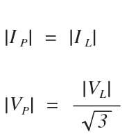
If it’s a delta system, phase voltage equals line voltage, but we know the phase current is √3 times smaller than line current:
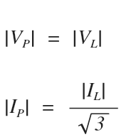
Lets see what happens when we substitute our line values into the formula, and manipulate it to get the square root three out of the bottom position of a fraction:
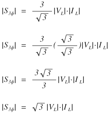
And Voila.
that’s all there is to it.
Would you like to share?
Comment below and share your experience dealing with the square root of three for the Electrical Power PE Exam.
Be sure not to give away any specific exam questions or answers per the NCEES policy.


Wye and delta configurations have been a constant source (no pun intended) of weakness in remembering when to convert voltages and currents to line versus phase and then dealing with single and 3 phase equivalents. This has definitely be a frequent reference in solving these types of problems.
Regardless still a great pun.
Thanks for the feedback Karli
Very informative article, not only do I have a better understanding of this Beast but I now have an appertain for it as well!
At first I wanted to say it is one of the best answers on this topic but then I knew that it is THE best answer for the square root 3 dilemma!
Glad you liked it! It was a big eye opener for me when I first worked out the math and I could not find any other articles on the subject so I knew it would help others.
When I was in college professor told me line voltage is root three time phase voltage and both phases are 120 degree apart. I kept this in mind. never look back and try to find why root. all though polar addition where there in maths separately. thanks for informing.
Regards
Mukesh
Chutiya hai sala ye
Super sir
That pesky square root of 3! Zach, your dedication to understanding and explaining topics such as this one have really helped build my confidence as I prepare for the exam because it shows how dedicated you are to your craft and to helping others such as myself.
Thanks for the kind words, we enjoyed having you in our program this semester. Best of luck on the PE exam and please let me know if I can help you in any way in the future.
Good explanation
Question, what would the value of Vp and Ip be? RMS or the real value seen on an oscilloscope (peak voltage and peak current) ? You see, I’m trying to calculate the Bemf and Torque constant (Ke and Kt respectively) with the gathered data from a motor simulation such as FEMM. It seems unclear if I need to square root 2 each line voltage as per peak value. Example, I have a 144Vdc link to an inverter. If I ignore the losses in the inverter, I would get 144Vac on each terminal phases for a 3 phase machine. However, my Kt does not agree at all with the Ke. According to text, Ke=Kt if we ignore all losses. It would ne appreciated if we could have numbers on does variables! 🙂
Regards,
Donald W.
144Vac should read 144Vpeak.
Hi Donald, good question. |Vp| and |Ip| are the magnitude values of the phasor represented in RMS. If you need to use the peak values of the instantaneous function for your calculations you’ll need to factor in the √2 multiplier to convert from RMS to peak.
for the past 4 years that I’ve been studying power, I’ve never fully understood why we use root 3 (I won’t lie, I failed a graduate level exam because I’d mixed it up.) This example was so easy to follow to the point that even though I understand the concept now, this is in much better terms than I’d be able to use, making it such an easy reference. Highly recommend printing this out and having it in your office if you work in the power industry!
What should be the answer to following situation:
There is a main switch board where 3 ph 220 volts enters from the distribution line.
The value on the 3phase KVAh meter after one month shows 600 KVAh consumed.
Line R consumed single phase 220 volts about 200 KVAh
Line S consumed single phase 220 volts about 175 KVAh
Line T consumed ???
Can it be calculated like capacity 600 – 200 – 175 = 225 KVAh
I doubt it as this is an unbalanced situation.
Please could you explain me how to calculate?
I can honestly say it took writing down the equations and solving the problems to remember and understand the sqrt 3 vs. 3. Also, your re-explanation during the live classes have been very helpful!
The step by step instructions in this article are great! After reading this and watching your in-class explanation, the sqrt(3) makes much more sense.
At first you say V_Bn has an angle of +120 then immediately afterwards you draw a phasor diagram showing the angle as -120.
Hi Josh,
Thanks for bringing this to my attention. This is one of our first articles and it appears that mistake has been there for quite some time. I just corrected is so that VBN has the correct angle of negative 120 degrees, and VCN has the correct angle of positive 120 degrees. I also updated all of the diagrams since they were previously hand-drawn.
Hi Sir,
In p.u. system Ib =Sb/Vb or Sb/sqrt3Vb which is correct and why ?
Hi Imran,
My apologies for the late reply.
When working in the per-unit system [pu], there is no square root of three since the square root of three will be included in the base values when you convert from per unit back to actual values.
This means for single-phase AND three-phase systems, line current in per unit is:
Ipu = Spu/Vpu
When working with base values in actual units (such as ohms, amps, and VA), then there will be a square root of three if the formula normally calls for it depending on the system type.
This means the base current for a single-phase system is:
IB = SB/VB
and the base current for a three-phase system is:
IB = SB/( √3 VB)
More information on where the square root of three for the previous formula comes from can be found here:
https://www.electricalpereview.com/biggest-mistake-commonly-made-three-phase-power-formulas/
Can you describe how to find the other, Vbc and Vca. because the angle of the rest is different to actual angle
Hi Redo,
It follows the same process. Let’s use an angle of zero degrees (0º) for the A-phase voltage (VAN).
Let’s assume balanced conditions such that the magnitudes of all phase voltages are equal:
|VP| = |VAN| = |VBN| = |VCN|
And positive ABC sequence conditions such that if VAN has an angle of zero degrees (0º), then VBN lags by 120 degrees (-120) and VCN leads by 120 degrees (+120º).
Using Kirchoff’s voltage law we can solve for each of the line voltages as the sum of their phase voltages (it helps to look at the wye connection when you write these):
VAB = VAN – VBN
VBC = VBN – VCN
VCA = VCN – VAN
Let’s use a magnitude of 1 volt for all line voltages and fill in their angles accordingly to simplify the math. Use your calculator in polar mode to the final answer:
VAB = VAN – VBN
VAB = 1V<0º - 1V<-120º
VAB = √3<30º
The A-line voltage magnitude |VAB| is larger by a factor of the square root of three compared to the A-phase voltage magnitude ( |VAB| = √3•|VAN| ) and it leads the A-phase voltage angle by 30 degrees (0º + 30º = 30º).
VBC = VBN – VCN
VBC = 1V<-120º - 1V<120º
VBC = √3<-90º
The B-line voltage magnitude |VBC| is larger by a factor of the square root of three compared to the B-phase voltage magnitude ( |VBC| = √3•|VBN| ) and it leads the B-phase voltage angle by 30 degrees (-120º + 30º = -90º).
VCA = VCN- VAN
VCA = 1V<120º - 1V<0º
VCA = √3<150º
The C-line voltage magnitude |VCA| is larger by a factor of the square root of three compared to the C-phase voltage magnitude ( |VCA| = √3•|VCN| ) and it leads the C-phase voltage angle by 30 degrees (120º + 30º = 150º).