There is a lot of confusion surrounding the per unit system, and rightfully so. If you’ve never used it before, it is easy to become confused with all of the individual pieces that make the system work.
To help clear things up, here is an in-depth break down on an example question that is similar to what you can expect to see on the NCEES Electrical Power PE Exam.
Related Per Unit Articles:
Electrical PE Review – Base Changing Percent Impedance and Per Unit Impedance
Electrical PE Review – Calculating Base Impedance with Three Phase vs Single Phase Values
What’s in this article? – Per Unit Example – How To, Tips, Tricks, and What to Watch Out for on the Electrical PE Exam:
Click below to jump to any section.
- Per Unit PE Exam Practice Problem
- Step 1: Separate by Voltage Zones
- Step 2: Assign Base Values
- Step 3: Calculate Base Impedance for Each Zone
- Step 4: Calculate the Per Unit Impedance for Each Zone
- Step 5: Calculate the Per Unit Impedance for Transformer T1
- Step 6: Calculate the Per Unit Impedance for Transformer T2
- Step 7: Calculate the Per Unit Current and Per Unit Voltage
- Step 8: Use Ohm’s Law to Calculate the Per Unit Current
- Step 9: Calculate the Base Current in Each Zone
- Step 10: Calculate the Actual Current in Each Zone
- Step 11: Check Your Work Using the Transformer Ratios
- Step 12: The Completed Diagram
1. Per Unit PE Exam Practice Problem
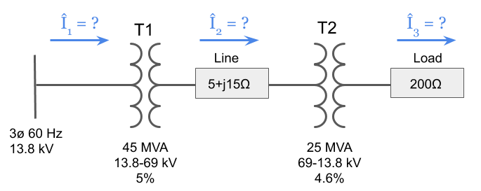
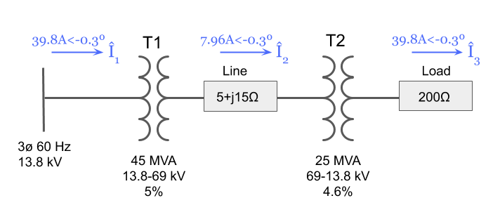
Using the Per Unit system and taking into account the transformer percent impedances, solve for the current in each part of the three-phase system shown below. Assume both transformers are either delta – delta or wye – wye connected and that there is no phase shift between primary and secondary current and voltage.
Step 1: Separate by Voltage Zones
The usefulness of the per unit system is in converting all system impedances to per unit impedances and re-drawing the circuit without having to worry about the different voltage levels from each transformer.
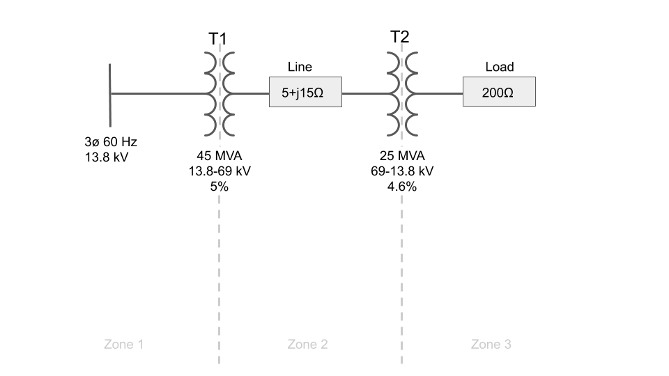
In this example, there are two transformers that divide the system into three different voltage zones that are created by the stepping up or stepping down of voltage by each transformer.
The first step is to illustrate this by drawing a straight line through each transformer:
Step 2: Assign Base Values
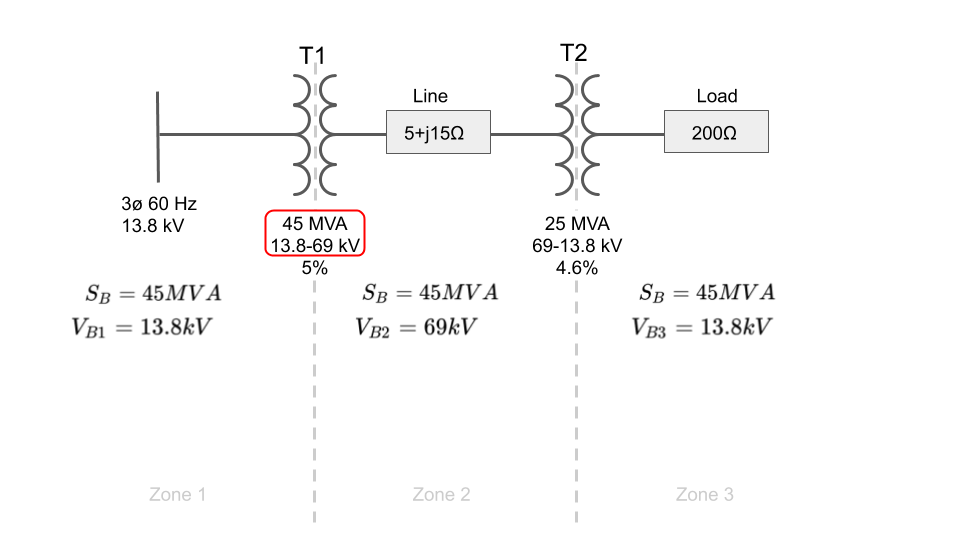
The next step is to choose the base values for power and voltage.
The base power will be the same in for each zone, but each zone will have a different base voltage.
The problem might tell you to use specific values for base power and voltage. If it does, use them accordingly as the answer choices will most likely still be in per units and using a different base will change the resulting per unit system values.
If the problem does not assign the base values for you, then it is advantageous to pick one of the existing MVA values in the system such as the apparent power rating of one of the machines.
Similar for voltage, it is advantageous to pick one transformer and use either the primary or secondary voltage as the base voltage in a particular zone, and then use the remaining transformer ratios to step up or down the voltage base for each neighboring zone accordingly. Why this is advantageous will become clear when we run the math.
If all transformer ratio’s match, then the secondary voltages of all upstream transformers are equal to the primary voltage all downstream transformers and vice versa, then your voltage base in each zone will be equal to the primary and secondary voltages of each transformer. That is the case for this example.
For base power, I’ve arbitrarily picked T1’s MVA rating for the system and the voltage ratios of the transformers for the base voltage in each zone:
Step 3: Calculate Base Impedance for Each Zone
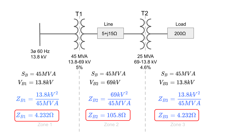
Now that we have the assigned base values for power and voltage, we’ll need to calculate the base impedance for each zone so that we can use it to calculate the per unit impedances later on.
The formula for base impedance is:

We can solve for impedance using voltage and power, and if we use the base voltage and base power in each zone, then the resulting impedance will be the base impedance for each zone as shown below:
Step 4: Calculate the Per Unit Impedance for Each Zone
Now that we have calculated the base impedance for each zone, we can start calculating the per unit impedances of each system element using the following formula:

We will start by calculating the per unit line impedance and per unit load impedance first before we tackle the transformers.
The line per unit impedance and load per unit impedance are calculated as shown below:
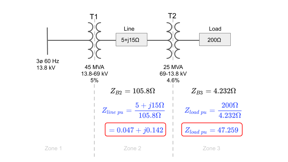
Now that we know the per unit line and load impedances, let’s draw them on the per unit circuit diagram:

Step 5: Calculate the Per Unit Impedance for Transformer T1
In order to complete the above diagram, we’ll need to calculate the per unit impedances of both transformers T1 and T2.
The catch here is that we don’t know either of the transformer impedances in ohms, we are instead given their percent impedances.
When you are given the percent impedance of a machine such as a transformer, generator, or motor, the percent impedance is given in the base ratings of the machine itself.
This means that in order to calculate the percent impedances of the transformers, we actually need to perform a per unit base change using the following formula:

In this case, the old base will be the ratings of each transformer, and the new base will be the new bases we have chosen.
Since we are working with impedances, we will need to plug in the impedance formula that uses the square of the voltage divided by power:

In the above formula, S BASE NEW and V BASE NEW will be the chosen bases of our system and zone, and S BASE OLD and V BASE OLD will be the transformer voltage and power rating.
Transformers have one power rating, so choosing that is easy. However, they have two voltages, a primary and secondary.
If we use the transformer’s primary voltage for V we will need to use the base voltage on the primary side of the transformer for VB in the formula above.
If we use the transformer’s secondary voltage for V then we will need to use the base voltage on the secondary side of the transformer for VB instead.
This will be more clear when we work out the math below.
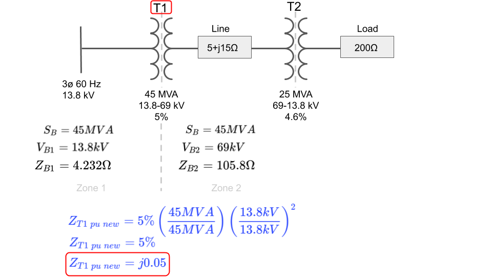
Let’s base change each transformer’s percent impedance one at a time starting with transformer T1 using the primary voltage rating as V and the voltage base on the primary side of the transformer for VB:
Step 6: Calculate the Per Unit Impedance for Transformer T2
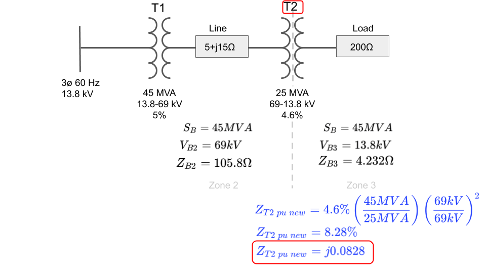
Notice that since we originally chose 45MVA as the base power for the system, both power terms are equal and cancel. This will not be true for T2.
Also, notice, that both voltage values are also equal and cancel since the base voltage in each zone is equal to each transformer’s voltage ratio.
It is important to be aware that the voltage values in the above formula will not cancel when the actual voltage in a zone is not equal to the transformer’s voltage ratios such as when a generator is connected that supplies a voltage slightly higher or slightly lower than the primary voltage ratio of the transformer it is connected to, or, when all transformer ratios do not match as mentioned in the first several paragraphs.
Notice that since our base power and base voltage for T1 equal the base values we were changing to, there is no actual change in the percent impedance. We started with 5% and ended with 5%.
Last bit of importance is to notice the imaginary “j” term placed in front of the final per unit impedance value for T1.
Transformers are made up of large inductive coils and their impedance is mostly reactive.
The PE exam may not remind you of this and it will be up to you to not only recognize that this is actually a reactive impedance but to also add the imaginary j term to it.
Let’s move on and calculate the per unit impedance for transformer T2:
Step 7: Calculate the Per Unit Current and Per Unit Voltage
Now that we have both per unit impedances let’s fill in the remaining values in our per unit impedance diagram.
Again, notice that both transformer per unit impedances are reactive terms and we had to add the “j” multiplier:

Now that we have all impedances converted to per unit values of the same base, it’s time to calculate the per unit current using Ohm’s law:
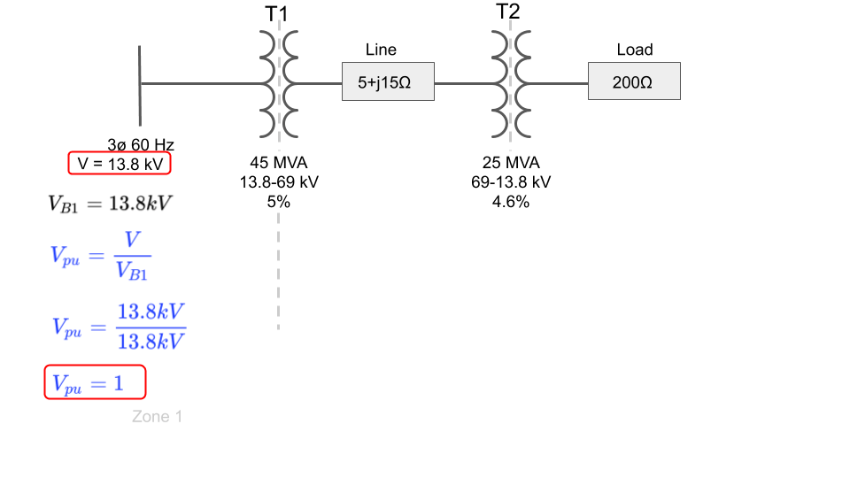
However, in order to calculate the per unit current, we will need to calculate the per unit voltage.
Luckily for us, the voltage on our input bus is equal to the base voltage selected in that zone which simplifies the math since both terms cancel:
Step 8: Use Ohm’s Law to Calculate the Per Unit Current
Since the input voltage is equal to the base voltage in zone 1, the per unit voltage at the source of our per unit impedance diagram is equal to 1.
This greatly simplifies solving for the per unit current which will now equal the inverse of the total series per unit impedance of the system:
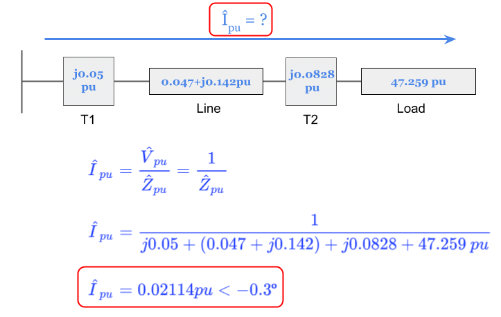
The per unit current will be the same value for each voltage zone.
Step 9: Calculate the Base Current in Each Zone
Now that we know the per unit current, we can finally calculate the actual current in each voltage zone by multiplying by the per unit current by each base current:
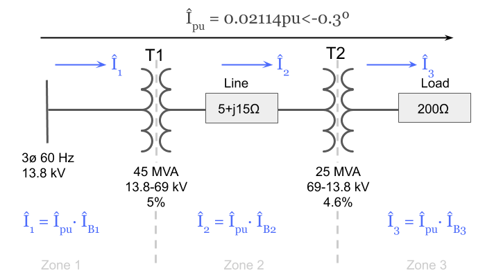
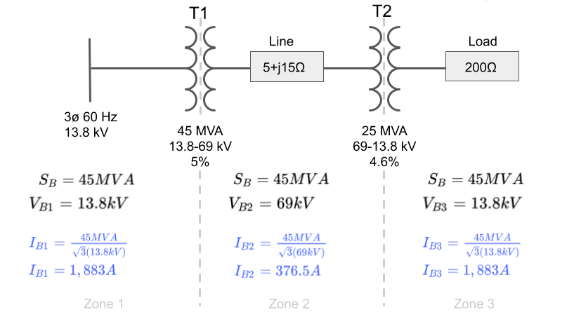
However, this requires us to know what the base current in each voltage zone is equal to.
We can calculate it using the chosen base power and the chosen base voltage in each zone as shown below.
Notice the √3 multiplier since it is a three phase system:
Step 10: Calculate the Actual Current in Each Zone
Now that we have each of the base current values we can complete the problem and solve for the actual current in each zone in amps:
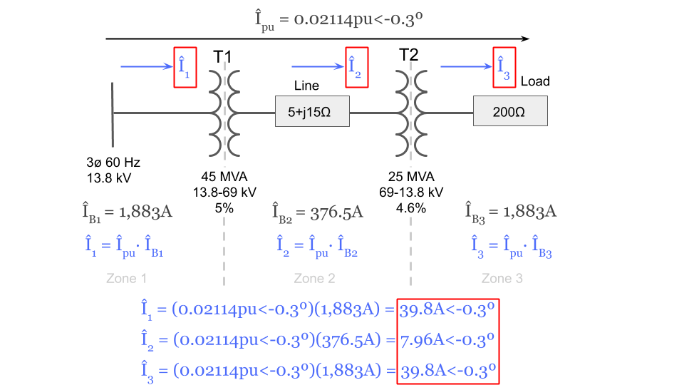
We can now fill in the current in amps for each zone to the original system diagram that we started with:
Step 11: Check Your Work Using the Transformer Ratios
For a quick check of our work, we can use the transformer voltage ratios to verify our currents are equal in each zone depending on voltage level.
If we did our work correctly we should get almost the exact same answer for each current by starting with one and using the transformer ratios to solve for the rest
Let’s start with current I3 and work our way back to I2 and I1:
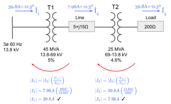
Looks good! Everything checks out.
Step 12: The Completed Diagram
Here is our final answer solving for the individual currents in amps of the original system using the per unit method:

Hope you enjoyed this exercise using the per unit system.
Related Per Unit Articles:
Electrical PE Review – Base Changing Percent Impedance and Per Unit Impedance
Electrical PE Review – Calculating Base Impedance with Three Phase vs Single Phase Values


Hi Zach,
I got familiar with your website and the course you provide on YouTube just two weeks ago. I absolutely love listening to your lectures and solving the the quiz problems (the free courses). I wish I knew about your website at least 2 months ago! Never the less, I highly recommend people to go over your course, as you go over concepts and basics and not just to pass the exam which I appreciate a lot. I am a first time taken and have benefited from the free videos you have posted.
The PU problem was very well and neatly explained with all steps. I do not have a problem with PU, but I was still glad you posted something. Keep doing the good work! You are a great instructor. Thanks for your help. Fingers crossed I pass.
Thanks for the complements Ria! Good luck on the October exam. If for some reason you don’t pass this time around and need some extra help, you know right where to find me.
Good job sir i real appreciate your work you a life saver 🙏🙏
I fully agree with the Ms.Ria for her compliments to you. You are a great instructor, sir. The way you have explained the step by step procedure in your example for finding the zone-wise currents reminds me of my best teachers !
Just a question I have in mind : Suppose the load of 200 Ohms at end is replaced by a 13.8kV Bus and a dead 3ph short ckt occurs there, how will we find the zone-wise short Ckt currents using the pu method? If you could explain please .
Hi Zach,
Thank you so much for the thorough explanations on this topic. PU calculations are one of the most important and fundamental concepts in Power System modeling and Protection Systems. We were running Transient Stability Analysis utilizing PSS/E the other day at our office and we were given the machine’s data in machine’s base. However, the line data provided from transmission planner was given in system’s base. It was easy to enter the values in program and move on with the simulation but we verified the simulation results with the technique you explained above and the outcome brought smile to our face! Thanks for your help and keep up with awesome work!
That’s a neat story Maysam thanks for sharing, I’m glad the information in the article helped you and your colleagues!
Hi Zach,
Great article on the PU method! The way you broke down the process is both simple and effective. Following you methods has helped mitigate any small errors that could be difference between getting the question right versus getting the question wrong!
Thanks Patrick, I’m glad it helped!
Zach,
Thanks for posting this. Per Unit analysis has definitely been one of my most challenging concepts to consistently perform correctly. I’m definitely going to use this during my last couple weeks of preparation before the test to hopefully solidify my understanding of per unit problems.
Hi Seth,
I’m glad the article was helpful!
This is wonderful. It was the easiest way to understand one of the most complected topics for me.
Glad it was helpful Anmar!
Thanks for posting Zach! The way you break down the different steps based on the different sections of the system is very helpful! It simplifies per unit analysis tremendously.
Thanks for posting. Since PU method is not my favorite, but with this example makes easier to understand and follow the steps to solution. what a great example and hopefully able to solve PU problems during exam.
What a great article! Per unit can be very intimidating, but I’m feeling confident after these examples. Thanks!
Thank you for posting this Zach, you simplified the PU and going step by step with all the explanation made it very easy. I feel very confident that any question in Per unit will be a piece of cake. it could have not been described better. thanks again
Very thoughtful and precise! Helped me to divulge my understanding of PU calculation, very detailed explanation so that I can easily follow.
This is just the beginning of what else ElectricalPEReview.com offers. Everything has been very helpful and help me understand PU analysis and much more. Thanks Zach!
Thanks Orlando!
Excellent article on per unit analysis. Between this article and your live webinar I feel much more confident solving per unit analysis problems.
Hi Zach.
Once again, my course work in the Electrical PE Review has helped to clear up my confusion in problem solving. This time regarding the PU System performed on a complex transmission line consisting of two series transformers, step up and step down configurations. The solution for this problem was presented step by step in a smooth and coherent fashion. Specifically, the technique shown of drawing a vertical line below each transformer, separating out the base voltages and power, allowed me to see more clearly what information the problem had presented me and what information was left for me to solve. I will use the technique going forward both in the PE Exam and my own future circuit analysis. Thank you again!
You are welcome, thank you Jeff!
Very helpful and complete discussion. I was always confused about the different bases, and struggled to pick one; but now it has become a whole lot clear. I specially like the discussion on the MVA method. Thank you for doing such a great job!
I really like how you’ve laid out this problem; though I can’t imagine a problem this long on the actual PE test. I’m following well up to the point where you simplify Ipu. That step could use some explanation. It might be good to add a step where you multiply by the complex conjugate and convert to polar notation to get the simplified answer for Ipu.
Thank You!
Hi Will, thanks for the comment.
I agree that this is not a 6-minute problem that you’d likely expect on the actual PE exam.
However, you could definitely expect to see any number of quicker to solve but still challenging per unit problems that are designed to be explained and demonstrated by this single, more in-depth, example. It was a way for me to compact a series of helpful lessons for per unit analysis contained within a single article.
Do you mind pointing out which exact step you are referring to with simplifying Ipu? If you do, I’d be happy to expand on it in both the article and here in the comment section as an update.
Thanks!
Toward the end of the article, you indicate your currents are off due to rounding when checking your currents in each section using the transformer voltage ratios. The error is actually due to using the incorrect current 2 base value in your current 2 calculation (you used 367.5A instead of 376.5A). This leads you to calculate I2 as 7.8A as opposed to 7.96A.
Very helpful, concise, easy to understand article on how per unit analysis works; greatly helped me. Thank you!
Hi Justin,
you are absolutely correct! Great catch, that was bothering me for a long time when I made the article because it should have been identical. Thanks for taking the time to point this out, I went and corrected the values. I’m glad you enjoyed the article on per unit analysis.
I have printed this article and often find myself referring to it when I get confused with how I should be calculating per unit values. Excellent resource.
Glad you enjoyed it Abhisek. Best of luck on the PE exam!
This topic was very presented. It was very easy to follow and understand. Thanks
I am no longer afraid of the per unit method. Thank you for the detailed step-by-step explanation!
This article was a game changer for me!!! I really appreciate the simple explanation that no professor or college has been able to provide until now. Thanks Zach!!!!!
You are welcome Michelle, glad you enjoyed!
Per unit was a weak area that I had when I started my preparation. The process you laid out above takes away a lot of the gray are that several sources that we have acquired during our preparation failed at filling. This example really embodies the value your service provides.
As always, I appreciate the kind words. From one Zach to another, best of luck on the PE exam.
Zach, this full length great example made it easy for me to solve any Per unit question and made me more confident in my practice. thanks
Glad it helped Rania
Best problem solving ever!
Thanks!
great explanation, i use your method know and so easy to understand, and so helpfull
Per unit calculations are much easier to solve for me with your detailed explanations. Excellent quality material. Thanks Zach!!!
You are most welcome Alex
Best explanation ever!
Great thorough example! this is an area that gives me trouble, i think mostly because it feels overwhelming. having this reference has helped break down the steps to help me isolate where i go wrong during other practice problems
Anything new always feels a bit overwhelming and unfamiliar. As long as you can work your way through this problem with confidence then you will be in good shape for the majority of per unit problems you might see on the PE exam.
Makes per unit method simple to understand on this article.
Excellent Article. Thank you very much Zach!
I believe that all the possible ‘land mines’ for per unit testing in the exam are covered by this article. The simplified approach is very intuitive.
Almost! I’ll likely put out another to cover the rest but I’d say this is about 90% of them. Glad you enjoyed it Mike.
Every other book I look at there is always a skipped step in the solution. This explains it very well.
Hi Phillip, I agree. Books skip a lot of skips because they assume you know every detail. It’s very frustrating. Glad you enjoyed the article.
The take away from this is if you see more than 1 transformer, ZONE! Draw that line!
If it is a per unit problem, then absolutely Julius.
This is the best explanation of all possible situations that I can encounter on the examwith per unit. I reviewed this article a while back and printed it. I plan to review again to keep it fresh before the exam! Most references leave out pertinent steps…this provides me with all the steps involved! Thank you!
Never had a course over per unit in college, but 30 minutes later, I can now say I have some confidence on how to approach and solve per unit questions on the test. Extremely helpful!
This is a great article. When I first started studying for the PE exam, per unit and MVA methods were new to me. I printed this long before your live webinar course started for me so I’m glad I looked at this early so I wasn’t out in left field!
Solving through this problem and article step by step helped me with understanding the different voltage bases and how to chose them.
This document reveals the secrets of Per Unit. A scary topic for many electrical engineers. Take it with you to the PE Exam and you will benefit a ton out of it.
this article helped tremendously on the per unit steps and issues. It’s helped me understand per-unit to the most basic level.
thanks Zach.
This pretty much explains every question that anyone might have on per unit. Great article.
Thanks!
Very simplified explanation! Thanks Zach
simple explanation, easy to follow and better understanding. Thank you Zach
This was another subject that I simply had trouble understanding before reading through this article and taking the review course. Zach’s explanation makes much more sense than the way per unit analysis was explained to me before, and his use of “zones” that are broken up by primary/secondary sides of transformers made all the difference!
PLEASE COMMENT ON THE DIFFERENCE BETWEEN THE USE OF IEC STD. 60909 IN THE CALCULATION OF SHORT CIRCUIT CURRENT FAULTS VIA IMPEDANCE METHOD AND THIS PER UNIT METHOD BY ANSI/IEEE.
Hi Felix, I understand you are looking for help however this is outside of the scope of the PE exam. Also, please refrain from using all caps in the future or your comments will be deleted. Using all capitals is the online equivalent to shouting.
I can solve PU values all day long! I have solved at least 30 questions with correct answers. My question still remains which I asked in single phase/3 phase impedance.
The calculated I1, I2, I3 PU values in this example are line values. correct? They can’t be phase values as the problem doesn’t even say what is the configuration of the transformer. How come we are using 3 phase transformer values, 3 phase load values and per phase line impedance? I would think either you would use all per phase values or 3 phase values and then use the square root 3 to determine whatever you need to determine. This is driving me nuts!! The above is a single phase representation of 3 phase network, then why we use 3 phase KVA and voltage values?
Hi Mark,
Correct that the per unit current values solved for in this example are line values.
I think the key here that you may be missing is that impedance values are always “per phase” values. Impedances are always going to be one of three things: the impedance “per phase” on each line conductor, the impedance “per phase” in each phase of a delta connected three-phase load, or the impedance “per phase” in each phase of a wye connected three-phase load.
Base values can be chosen arbitrarily, and using the three-phase power for the overall power base, and the line voltage in each voltage zone as each voltage zone base tends to simplify the per unit calculations.
I understand that this can all be one giant headscratcher when combined with the per unit system and your question is one that comes up often. Until it’s worked out in front of you and explained in a setting where you can ask questions live it can be elusive and very much so counter-intuitive.
Are you a current student of ours? Your specific question is a key part of the per unit system that we dedicate undivided time to explaining live during our online class on the per unit system.
This semester’s live class on the per unit system is currently scheduled for March 3rd, 2019. For more information please visit the Live Class course on the following course catalog page: https://courses.electricalpereview.com/ . Live classes are currently included as a free bonus and bundled with our premium online review course. In the future, it will be priced out as a separate product.
I hope this helps.
Hello Zach,
Thank you for the explanation. I have flagged your site for future review as well.
Two questions.
1) How do we convert y to pu? Do we just invert the z-base and use that as a y-base?
2) How do we convert P and Q to pu? I remember that we simply divide by S-base, but then this morning I wonder if I need to find the S using the S=sqrt(Psquared+Qsquared). Can you please let me know which is correct?
Thank you,
Wende
Hi Wende,
Glad you’ve found our material useful.
1) To convert admittance (Y) to pu, you need to find the admittance base which in most cases you are correct will be the inverse of Zbase for that particular zone.
2) Just like converting the real or imaginary components of a complex number to pu, you just divide each of the components by the base value of the quantity. Base values are magnitudes. For example, to convert R and X to pu, you would divide each by the base impedance, Zb:
Rpu = R/Zb
Xpu = X/Zb
Similarly, to convert P and Q to per unit, you just divide each by the base apparent power, Sb:
Ppu = P/Sb
Qpu = Q/Sb
Hope that helps.
I find this per unit example article to be extremely helpful to me since I struggle with this topic and fumble through it only to derive the wrong answer. This is a well designed article and would recommend that others would read through it to gain a better understanding of this concept and of course pass the PE exam. Thank you for a job well done Zach!
I’ve already added this to my references! I definitely appreciate the additional time you’ve taken to break down the PU method for us. I’m an MVA guy so this is great, thanks again Zach
Definitely printing this one out and putting it my references, clarifies a lot!
This awesome free article helped me get a solid understanding on Per unit. I have bought a lot of reference materials for PE exam but I don’t think any materials/book explain per unit better than this free article. Thanks to Zach.
Solving the problems using PU is not intimidating any more. I fully understand the concept and the two methods used to solve for any calculation: Finding the fault at point x in the system, or looking for Voltages and Currents at any given point in the system.
Great article. helps clear up a lot of question I had. thank you
This is probably one of my favorite articles from electricalpereview.com. I used to have a lot of trouble with the per unit system, but the way Zach splits up the voltage zones and explains each step has really helped me understand the process and solve problems correctly. Definitely printing this out to bring to the exam!
This article does a great job of breaking down a confusing topic and exhaustively explaining every single step. Great Job Zach!
Thanks for the help! I actually understand Per Unit now. AWESOME!!!
I was always confused what MVA value to use for these types of problems. These examples cleared that up quite quickly. Thanks!
What a helpful article. Using per unit to solve problems were more challenging for until I read this article. Showing how to divide the system into different sections and selecting the best base voltage and apparent power make these problems much easier.
Probably one of my most feared subjects before this article, but not anymore. I hope i see a lot of per unit on the exam!!!
This is a subject that I avoided, but with Zach’s help and this article, I feel I can state it finally makes sense. Thanks for the help!
This is hands down the best course you can take to do your best at the PE exam. It prepares you, its well explained and gives you many tools to do your best. In addition, Zach is always available to answer any questions. Absolutely a great course. I highly recommend it!
This was an excellent explanation. This article was really helpful.
I have one question: How would the calculations change if T1 was delta-wye and T2 was wye-delta?
Hi Zach
Excellent Article with simple explanation, easy to follow for better understanding. It is awesome by dividing the power system into different sections and the calculation into steps for the best explanation of the problem solving.
I did not find any materials/book explain per unit better than this free article.
For doing such a great job, Thank you very much Zach!
Thanks for the kind words Mohamed, I’m glad you enjoyed the article.
When I took my PE exam in April, I relied too much on solutions and didn’t really learn how to apply the method of PU Analysis. I got overwhelmed with all the conversion back and forth into different bases. This actually was a great resource to simplifying the material. Thank you!
This guide helped clarify many points that were fuzzy for a long time. I can now focus on the rest of the exam question instead of getting spooked by the PU portion.
thank you for your acticle.
Taking the time to break PU’s up into zones really helped organize and understand how to tackle each problem, thanks
Thanks for breaking this topic down and making it easier to follow thru. Keep up the great work Sir. Great job!!
Step by step breakdown helped me understand this topic. Great article. Thanks Zach.
Such a great walkthrough! I put this in my PE reference material and I refer to it often when solving problems. Per unit was hard for me to wrap my head around but taking it step by step like this will solidify the fundamentals and is a great reference when I’m stuck.
Great help Zach! Per unit method is one confusing topic but your step by step method of solving this topic made it easier to understand. Thanks again for your help!
A must have in the exam. It help with base changing and explain things in great order.
Per Unit method makes you calculations really easy to set up. The tips and tricks in this article really puts everything into perspective for you.
Zach, I can’t thank you enough for this article. I was always a bit about p.u. concept especially founding base impedance but now that you make me understand it, I am sure that my level of confidence for p.u. method has increased and I am grateful that you made it this article free. Thanks again
Really enjoyed this article. Initially I just read it and followed along, and the explanation stuck with me – I came back to it some time later and was able to work through the example on my own. Per unit is not scary after all!
You have taken a pretty complicated topic and just made it understandable. Its great you put these articles together to help students like me who don’t deal with this stuff everyday.
I want help to solve some problems of per unit
This article makes it SO much easier to understand per unit compared to all other reference materials I have. Thanks Zach!
Thanks to this article, I now know how to solve per unit problems. This class really taught me how to analyze every problem with a plan of attack. Can’t wait for next week.
Hello. For the details seen here: “If all transformer ratio’s match” …. “That is the case for this example.” —- the first transformer has a turns ratio (secondary to primary) of 5:1. While the second transformer has a turns ratio (secondary to primary) of 1:5. So the first transformer ratio is ‘5’, while the other one is 1/5 or 0.2
Does that actually count as a ‘matching’ transformer ratio?
Hello again. I see what you mean by ‘match’ now. I think the meaning was two interconnected transformers having reciprocal turns ratio. Thanks!
thank you electricalpereview for giving me wonderful information
In step no 9, there was no requirement of dividing by root (3) while calculating Base value of current. Hence, final values of magnitudes of current should be => i1= 68.60A, i2=13.72A and i3= 68.60A.
Hi Sameer, thanks for your comment.
When working in the per-unit system, such as calculating the per unit current (Ipu), the square root of three is not used even for three-phase systems.
However, when working with actual units, such as calculating the base current in amps like in step 9 of this article, the square root of three is used just as you normally would for three-phase formulas, if you are working with a three-phase system.
The final values of the magnitudes of current are correct as shown in step 10.
If this was a single-phase system instead, then you would be absolutely correct and the square root of three would not be used for the formulas used in step 9 to calculate the base current.
Hello – could you please explain what the following means? Just above the third image of the articular, it says “For base power, I’ve arbitrary picked T1’s MVA rating for the system and the voltage ratios of the transformers for the base voltage in each section:”
What does ‘and the voltage ratios of the transformers for the base voltage’ mean? Thanks and regards.
Kenny
Apologies, I meant ‘article’ – not sure why it ended saying ‘articular’. Kenny.
Hi Kenny,
In order to work within the per unit system, all impedances must be converted to per unit using the same system base values.
For this particular demonstration, the base values of the system were chosen to match that of transformer T1, however this is arbitrary.
Any base values may be chosen and the results would still be the same when converting back to actual units (such as amperes, impedance, power, etc). Only the per unit values would change.
Thanks for your various articles. I had a basic question about the assumption of no phase shift in current and voltage. My understanding was that the presence of both resistance and reactance as shown in your example system would, in fact, induce a shift. If we assume there is no shift, I presume this method of solving the system is somehow independent of any real shift?
This following steps are very helpful in determination of the per unit, thank you so much sir
Glad you found it helpful.
i’m Fool in english !
but understand this Topic Very Well.
Just Can Thank you Dear Zach !!
me 2 ….
goh nakhor bro
Zach,
Where u state the following:
“Now that we have all impedances converted to per unit values of the same base, it’s time to calculate the per unit current using Ohm’s law:
However, in order to calculate the per unit impedance, we will need to calculate the per unit voltage.“
…I think you meant to put …However, in order to calculate the per unit current
Great catch Cynthia, thanks for bringing this to my attention, I’ve corrected this typo.
Man thanks a lot . I was out of my mind trying to learn this cause my professor messed this up. Thanks again for the simple explanation. Cheers.
Glad it was helpful for you DU.
Hi Zach,
Thank you so much. It was a great explanation. I got it perfectly.
Hi Mohammad, thanks for your comment. Happy to hear the per unit article above was helpful!
Hi Zach,
i have a Q about the PU system for a power system. For example, if i have a 3-Ph transformer with connection Y-D, i have to take in consider the phase shift of the transformer for the currents even if i´m in the PU system???
Great explanation by the way, thanks
what if both transformers have connected either delta – wye, and wye-delta, or vice versa
such a great explain, step to step, rechecked by turn ratio of transformer, respect you
Hey Zach, why exactly do we use the same S_base values for T1 when calculating %Z. But use different S_Base values for T2?
Hi Forest,
Thanks for commenting and my apologies for the late reply.
It’s because we are base changing the transformer impedance from the original base of the transformer to the new system base values.
In this example, I chose transformer T1’s ratings to use as the new base values of the system that we are converting all of the impedances to. That mean’s T1’s bases and the new base values of the system are the same.
T2’s power base is different and not equal to the base of T1.
More in-depth explanation with video examples about base changing per unit impedance and tricks to using the impedance base changing formula can be found on this article:
https://www.electricalpereview.com/base-changing-percent-impedance-and-per-unit-impedance/
This is an awesome tip/trick, very helpful and easy to understand.
Zach, Great article here taking a deep dive into per unit analysis.
My question is ( and it may seem elementary): The article mentions that transformers are made up of large inductive coils and their impedances is mostly reactive however I usually see X/R ratio’s between 3% to 10% in the field. My understanding is that the X/R ratio describes the amount of reactance divided by the amount of resistance of a transformer.
Does that mean that the transformer is mostly resistive than reactive since the X/R ratio is usually between 3% to 10% ?
Hi Moe,
The X/R ratio is another way of providing the impedance angle (θ) of the transformer winding impedance.
From:
Z = R + jX
The “X/R ratio” is just the reactance value (X) divided by the resistance value (R).
If you are given a transformer percent impedance (%Z) and X/R ratio, then you can also determine the percent resistance (%R) and percent reactance (%X) using trigonometry:
tan(θ) = X/R
θ = tan⁻¹ ( X/R)
Once you have the transformer impedance angle (θ) and the transformer percent impedance (%Z), you can convert from polar:
Z = |%Z| < θ To rectangular: Z = %R + j%X
Thanks for this example. I tried to solve it without using PU method:
Looking at all from the source towards the load:
Zone-2: (T2 a:1 = 5:1)
> load: R = 200 x 5^2 = 5000 ohm
> T2: X2 = Z2b * Z2% = (69^2)/25 * 0.046 = j8.76 ohm
> Zone2+3 total impedance = Z-line + R-load + X2 = 5005 + j23.76 ohm
Zone-1: (T1 a:1 = 0.2:1)
> T1: X1 = Z1b * Z1% = (13.8^2)/45 * 0.05 = j0.2116 ohm
> Z1+2+3 total impedance = X1 + (zone-2 total * 0.2^2) = 200.2 + j1.162 ohm
I1 = V1/(root-3 * total imp) = 39.80 < -0.33' amp
I2 = I1 / 5
I3 = I2 * 5
Great job sir.
If they give us 3 pase systems values, we have to conver it to the single phase diagram. what are changes we have to do in this case? is 3 pase power divide by 3 to get the single phase power?
This is very helpful.
A question.
Can we solve the fault current at the load?
Thank you sir , you are perfect instructor . Please could you send me the full notes in power system analysis 4th stage …