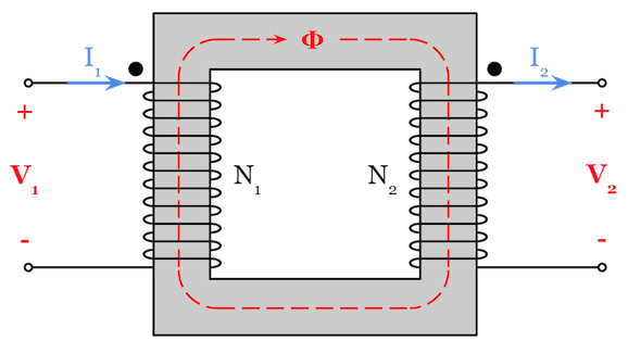
Transformer Magnetic Circuit Diagram
Magnetic circuits used to be one of my least favorite types of problems on the electrical power PE exam.
It seemed overly complicated and resources that taught this type of problem were hard to find without diving too far into the subject of physics, which is beyond what the PE exam tests on.
In this article, I’m going to teach you how to quickly convert any type of magnetic circuit into an electrical equivalent circuit so you can solve for any of the magnetic circuit variables using just the basics like Ohm’s law.
What’s in this Article? Click below to jump to any section:
- Transformer Magnetic Circuit, Flux, and Reluctance Practice Problem
- Dealing with Series and Parallel Reluctance in Magnetic Circuits
- Questions? Thoughts? Leave a Comment Below!
1. Transformer Magnetic Circuit, Flux, and Reluctance Practice Problem
First Let’s relate the magnetic circuit variables to the electrical circuit variables that we are more familiar with:
Magnetomotive force MMF (f) in the unit of ampere-turns [AT] is the magnetic potential similar to an input source like what voltage is for an electrical circuit.
Flux (Φ) in the unit of weber [Wb] is the measure of the magnetic field strength moving through an area, similar to how current (I) is the flow of electrical charge.
Reluctance (R) in the unit of inverse henry [H^-1] opposes and inhibits flux (Φ), just as resistance (R) opposes current (I).
Notice how the magnetomotive force (f) equation resembles Ohm’s law:

Now you’re ready to follow along with the practice problem in the video above by converting the magnetic circuit into an easier to solve the electrical circuit and using the magnetomotive force equation (f).
The practice problem in the video is:
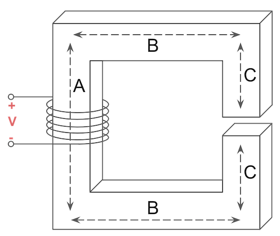
The transformer core shown below has an equal width along all parts, with each foot of core length equal to 2.5 H^-1 of reluctance. Solve for the total flux in webers circulating in the core of the below transformer If A = 2 ft, B = 2 ft, and C = 0.5 ft. The reluctance of the air gap is 4 H^-1, and there is a total of 10 ampere turns across the transformer windings.
The answer is flux (Φ) = 0.465 Wb.
Can you solve it?
2. Dealing with Series and Parallel Reluctance in Magnetic Circuits
We can combine series and parallel reluctance in a magnetic circuit just like we can combine series and parallel impedance in an electrical circuit.
To demonstrate just how easy this is, first convert the magnetic circuit into an electrical equivalent circuit and combine each branch of reluctance (R) one at a time until just the total equivalent reluctance (Req) value remains.
Once the total equivalent reluctance (Req) is known, you can easily solve for the total flux (Φ) or magnetomotive force MMF (f) in the circuit using the magnetomotive force (f) equation:
![]()
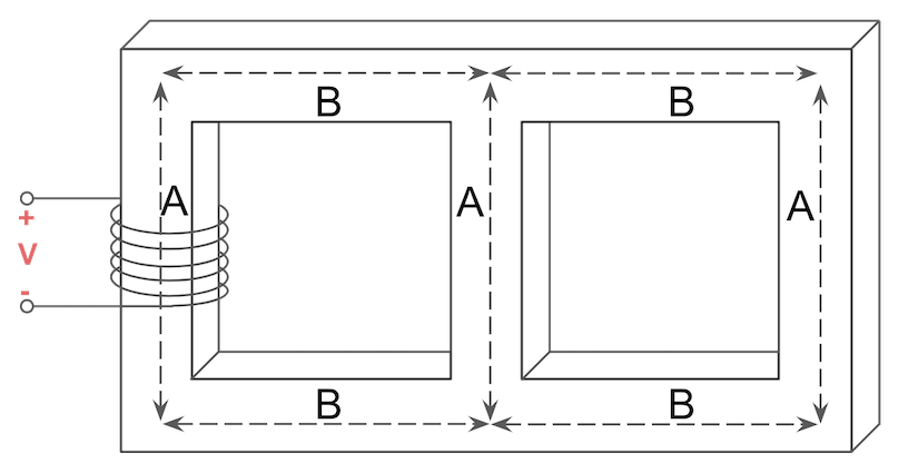
Try following along with the steps in the video to convert the following magnetic circuit into an electrical equivalent circuit, then come up with an expression for the total equivalent reluctance (Req):

The answer is Req = A + 2B + A//(2B+A).
Can you solve it?
3. Questions? Thoughts? Leave a Comment Below!
Have you had a difficult transformer magnetic circuit that you could not solve? Leave a comment down below and join the discussion.
For more practice with magnetic circuits, visit Chapter 7.1 Transformers in our online course for the Electrical Power PE Exam.


This blog is informative and the video of train having running on low volts has clear the concept. Love this blog.
Sir pls explain the concept for transformer used to compensate the voltage in line.