The following two rules will fix 99% of any mistakes you might be tempted to make with leading vs lagging power factor for the PE exam.
What’s in this article? – Leading and Lagging Cheat Sheet:
Click below to jump to any section.
- Power Angle Rule #1
- Power Angle Rule #2
- Lagging Power Factor Diagrams
- Leading Power Factor Diagrams
- Lagging Power Factor Example
- Leading Power Factor Example
- Print for Reference
Related Power Factor Articles:
1. Power Angle Rule #1
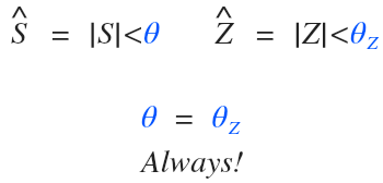
For a three-phase or single-phase system, the power angle (θ) of the circuit will always be equal to the impedance angle (θz):
2. Power Angle Rule #2
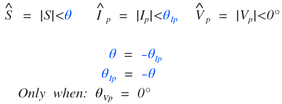
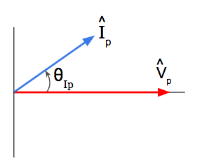
The phase current angle (θIp) is equal to the power angle (θ) except opposite in polarity when zero degrees is used as the reference angle for the phase voltage (θVp):
3. Lagging Power Factor Diagrams
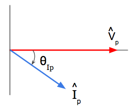
A lagging power factor means the impedance in the circuit is inductive and causing the phase current to lag the phase voltage.
This means our phase current has a negative angle when the phase voltage is at 0º
Let’s look at our phasor diagram for phase current and phase voltage, and let’s look at our power triangle for complex power when our phase voltage is at a reference of 0 degrees:
 |
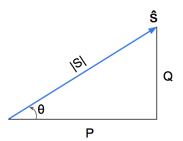 |
For a lagging power factor, the phase current always lags the phase voltage and the power angle theta (θ) is positive.
4. Leading Power Factor Diagrams
A leading power factor means the impedance of the circuit is capacitive and causing the phase current to lead the phase voltage.
This means our phase current has a positive angle when the phase voltage is at 0º.
Let’s look at our phasor diagram for phase current and phase voltage, and let’s look at our power triangle for complex power when our phase voltage is at a reference of 0 degrees:
 |
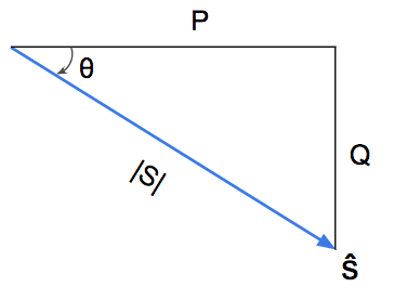 |
For a leading power factor, the phase current always leads the phase voltage and the power angle theta (θ) is negative.
5. Lagging Power Factor Example
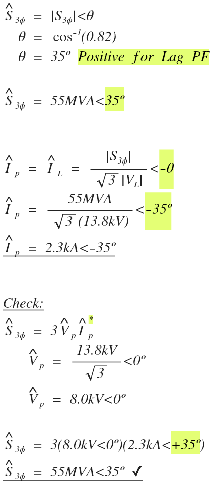
A three-phase, wye connected generator rated for 55 MVA and 13.8 kV is operating at full load with a 0.82 lagging power factor. Determine the complex line current delivered to the connected system using a reference of zero degrees for the system phase voltage.
We’ll use the three-phase apparent power |S3ø| formula and set it equal to current to solve for the line current (IL) of the system. For wye connections, line current (IL) and phase current (Ip) are equal, so we will use the result of this formula for the phase current to help us determine the angle for the complex current.
Since we are using a reference of zero degrees for the system phase voltage (Vp, or VLn), we will set the phase current angle (θIp) equal to the power angle (θ) and make the polarity negative (rule #2 above).
6. Leading Power Factor Example
A three-phase, wye connected generator rated for 55 MVA and 13.8 kV is operating at full load with a 0.82 leading power factor. Determine the complex line current delivered to the system using a reference of zero degrees for the system phase voltage.
We’ll use the three-phase apparent power |S3ø| formula and set it equal to current to solve for the line current (IL) of the system. For wye connections, line current (IL) and phase current (Ip) are equal, so we will use the result of this formula for the phase current to help us determine the angle of the complex current.
Since we are using a reference of zero degrees for the system phase voltage (Vp, or VLn), we will set the phase current angle (θIp) equal to the power angle (θ) and make the polarity positive (rule #2 above).
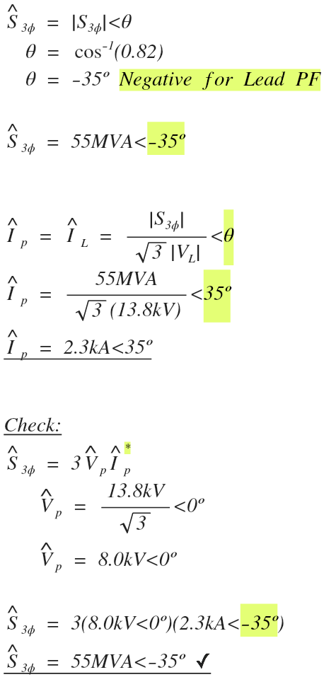
Notice the only variable we changed in each of the above examples is the power factor. The first example has a lagging power factor while the second example has a leading. All other variables in the problem were equal.
The only difference this resulted in is changing the polarity of both the power angle and the current angle.
7. Print for Reference
For a better print, highlight only the contents of the article then hit control + P and check “print only selected” under print options.
Enjoy.
(Go back to top)
Related Power Factor Articles:


On the leading power factor figures are your angles sign convention reversed?
Nope! I was trying to show that no matter what the current angle is always equal to the apparent power angle, except negative.
But I can see how this may be a little confusing, so I re-labeled the current angle as theta I to make more simple.
Zach Stone, P.E.
Thanks Zach for this illustration, it is very useful.
Glad it helps!
Thanks for the quick explanation/cheat sheet.
I got a bit confused on the leading example but after looking at it, I now understand you found the phase current then checked it by showing that the apparent power is negative the phase current.
Every Zachs’ presentations are awesome. Thanks for this one.
This is definitely going in my notebook. I know that the Apparent power angle = the Negative current angle but never put it together that its always that way.
I had a difficulty to understand the polarity for lagging current angle and apparent power angle. this article helped me to understand the difference between them. IT IS EXCELLENT WAY TO SEE THE DIFFERENCE. THANKS.
When S=VI*=IRI*=I2R. why the conjugate disappeared? Please explain.
Thank you,
Tony, I can’t attach pictures in the comment box so this will be a little harder to explain, but basically you are confusing two formulas that do not equal to each other. Let me explain:
Let’s look at each of the three equations you provided above that you set equal to S.
The first one is correct:
S=VI*
This solves for the single phase complex apparent power, which is the same as saying the single phase apparent power vector in polar form, so magnitude in volt-amps and angle in degrees.
The second formula:
S=IRI*
Is not correct. Because the impedance value is resistance (R), this will only solve for real power in watts, which has no angle, like this:
P =I²R
If you want to use the I² formula for apparent power S, you would need to write it like this:
S=IZI* = |I²|Z
where |I| is the magnitude of the current (no angle), and S and Z are both complex vectors in polar form.
The third equation you provided is also not correct:
S=I2R
I think you meant S = I²R, which is also not correct.
Again, I²R again will solve for real power in watts. Since real power (P) is just the horizontal component of the complex value S, it has no angle.
So to answer your question directly, there is no conjugate in the power formula:
P=I²R
Because Real power in watts does not have an angle, only magnitude (or magnitude with an angle of 0 or 180 depending on direction if you want to be precise).
Brush up on complex values of power, impedance, voltage, and current, then brush up on single phase formulas vs three phase formulas and I think it will be clear.
Make sense?
Zach,
Stupid question. when calculating Ip values in the above questions, why is there a squareroot 3 that was multiplied by 13.8 kV? isn’t 13.8 kV line voltage and the phase value would be 13.8/squareroot 3? Also, is there no need to convert the MVA value to KVA since the voltage is in kV?
Thanks..
No such thing as a silly question. Silly people don’t ask questions 🙂
Because we are solving for current using the three phase apparent power and line voltage. It comes from the formula for three phase apparent power magnitude:
S_3ø = √3VI
This article will be helpful:
Electrical PE Review – Avoid These Three Phase Power Formula Mistakes
Yes.
It was converted correctly. The only difference between MVA and KVA are the powers of ten.
M stands for mega and is equal to 10⁶
k stands for kilo and is equal to 10³
You’ll notice that the units of current are expressed in kA, or 10³ Amps.
2.3kA = 2.3•10³A = 2,300 Amps.
Love the cheat sheet! Figuring out leading and lagging PF is crucial to working out a problem correctly. Also, understanding the fundamentals of why a system is leading or lagging and if your power triangle is above the axis or below is crucial to the problem. Thanks for the help Zach!
Very informative! I am struggling with the lagging an leading but now I get it why capacitive is leading!
Glad it helped Ryndll!
This article is amazing! I spent hours studying leading and lagging. I kept confusing leading/lagging current/voltage and leading/lagging power factor angle. This article really cleared things up in just minutes!
Great quick reference to have for the exam. Thanks!
this is so far the most important concept which i never get to understand . so i finally sat clearing all my mind and just followed these steps. and the understanding i have now is to a level that i don’t even need cheat sheet to memorize the stuff. awesome explanation 🙂 10000 likes 😛
Thanks Shubpreet!
leading and lagging tends to be one of my best subjects, as you explained it too many times and made it very clear because I now understand it and no need for any memorization . thanks Zach
Zach’s detailed explanations accompanied by phasor diagrams may be the most important piece of learning for me to pass the PE exam! He taught me that leading versus lagging depends on the reference to power and current and to remind myself of that reference for each and every problem. I found that seeing every possible option for the power triangle, and phasor diagrams for voltage and current, drove the point home. Thank goodness he has so many different ways of explaining it! It’s best to jump in around 3 months before the exam so the stress level isn’t too high…
My understanding of leading and lagging has been transformed by this course, and this article will no doubt be a great quick reference to have for the test.
Thanks for the kind words Seth! I’m glad you’ve been enjoying the online review course.
Very helpful topic added to my quick reference guide.
This was one of the first items that added to my PE Reference Binder and one of the most helpful references for power factor correction problems.
By far my favorite article overall. Leading or lagging current, leading and lagging voltages, and then to also add power factor leading and lagging? Very confusing at first but after referencing this article multiple times it stick to you. Before you know it you’ll have it in your head. This article is a must when starting to study for the PE Exam and should be one the the very first ones you print out. Excellent explanation.
Thanks Eliseo!
Great to have these useful formulas in such an organized manner! A huge relief to have these during the exam. Thank you so much.
You are most welcome Eklas, glad it has helped!
Must have reference for the PE exam that has helped me out. Very easy to understand without allowing any chance for misinterpretation.
great article, it kick me and now i am better to understand
Glad it helped Egis. We enjoyed having you back in our online program, best of luck on the PE exam.
Drawing the power triangle helps solve and understand majority of the questions :).
This article ingrained that in me :).
This article makes the basics of leading and lagging power factor, power triangles even more easier to comprehend. It is very easy to confuse the sign conventions. Thanks Zach for such clear instructions. Definitely going in my 3 ring binder.
I definitely put this article into my binder. The two rules of deciding + or – on theta and Vp and Ip help a lot and take away a lot of guesswork on myself when doing any 1-ph or 3-ph S calculation.
I honestly thought I had a good enough grasp of leading and lagging power factor before taking this course, but now that I’ve gone through it, I realize that I didn’t know what I thought I did. This course helped me to understand what leading and lagging power factors mean for every aspect of the circuit, not just current to voltage, but also how it is controlled by the load and why we use the conjugate of our current in the appropriate apparent power formulas.
Great cheat sheet and explanation of the leading and lagging.
this has helped me get a down packed level on this rather sometimes confusing subject matter.
Just added to one of my reference binder, really good explanations and diagrams.
Another fundamental concepts. Everything has been explained sufficiently and left without question. This is a must have and the course itself is one of the greatest tools you’ll get once you have subscribed to it.
This is a must have!!!!!
Great Article! These fundamentals of Power Engineering are used in the PE Exam to trip exam takers. Thank you for always starting with the fundamentals and building a great foundation of knowledge which has given me confidence going into this PE Exam.
Don’t ask me how, but prior to this video, it did not click that leading and lagging were in reference to the CURRENT angle. This article did a good job of spelling that fact out clearly and as a result I feel less intimidated when I see said terminology, and drawing phasor diagrams seem that much easier as a result. One more weakness taken care of before the PE exam!
Leading/lagging and power/current angles was a fundamental topic that really tripped me up until reading this article and taking Zach’s course. Now it is like second nature!
Nothing confused me more than leading vs lagging power factor and the relationship between the voltage and current phase angles, the impedance angle and the power angle. Thanks for clearing things up Zach.
Zach, great article. This will be very helpful as a reference to the exam in case of any doubt!
My favorite article. This is a must know for the PE exam. Thank you for the article!
This is probably my favorite article on your website. I printed it out a while ago and have a specific tab for it in one of my binders in case I need a quick refresher on lead vs lag. It really helped my understanding of the relationship between impedance, apparent power and current phasors, when power angle is negative, etc.
Thank you!
This is perfectly laid out from start to finish. Understanding lead vs lag should be a no brainer if you have this cheat sheet with you on exam day.
Thank you! really needed this.
When a question says 55A current with a 0.85 Lagging power factor, does it refer to the current or to the apparent power?
Does Power Factor only refer to the relationship between real power and reactive power. or to the element in the question? will the angel be deferent if the question has 55MVA with a 0.85 Lagging PF vs 55A current with a 0.85 Lagging PF?
Hi Chaim,
There are a lot of questions in your comment, I will do my best to answer them one at a time.
Apparent power is the magnitude of complex power, by itself, it does not have a phase angle. 55 amps with a 0.85 lagging power factor tells you that both the complex power angle, and the amount of degrees that the current lags the applied voltage by is both equal to the inverse cosine of 0.85.
Power factor refers to several different things all at once. One of them is the ratio of real power (P) to apparent power (S): PF = P/S. I’m not sure what you are referring to with the use of the word “element”.
No. The power angle will be the same for 55 MVA 0.85 lagging PF load and a 55 A 0.85 lagging PF load. The only difference is the amount of power (or current) being drawn by the load.
Of the $1200 I spent on the 6 month Unlimited package……. this single cheat sheet (plus the power fundamentals boot camp) was worth $600 of that. I put all 7 of these notes/problems onto one sheet and referenced it through every single chapter studying. Helped me understand power immediately and intuitively understand 1ø vs 3ø and Δ vs Y.
Hi Brian,
Thanks for your comment!
Glad to hear that the leading lagging cheat sheet (this free article) and the Power Fundamentals Book Camp was worth 50% of the cost of the Unlimited Package enrollment.
Very nice summary of Theta and its relation to current angle! Maybe update the printing instruction to reflect CBT – no references allowed. But great study aid!
Thanks Mitch, great eye.
I will just memorize that phase current is lagging if it is in the 3rd or 4th quadrant given phase voltage as the reference at X axis for 1 phase circuit. Then the current phase angle is the opposite of that of the impedance and the power angle.
How is it known that 13.8 kV is line voltage, not the line-to-neutral or the phase voltage or even line-to-line? I know that an angle is not given does that make it definitively a line voltage unless otherwise stated?
The ratings of a three-phase system or three-phase machine, like the wye-connected generator in the problem, will always be given in three-phase line values unless explicitly stated otherwise.
I am having a problem understanding how, in the example, Vl was converted to Vp without shifting the phase angle. Shouldn’t there have been a 30 degree shift?
There is still a phase shift. In this example we are using a reference of zero degrees for the line-to-neutral phase voltage (Vp) which means the line voltage (VL, not shown on the phase diagram) would have an angle of +30º assuming a balanced and positive ABC sequence system.
Zach, I’m working through a single phase circuit with a wattmeter and your power angle rule #2 didn’t work when solving for power (W) and power factor. Does that rule apply for 1-phase and 3-phase circuits? And does that formula not apply to circuits with wattmeters? Seems silly, but I’m just trying to figure out when it’s not appropriate to use that formula. Appreciate your time and content!