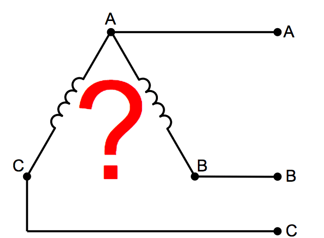
How much power can an open delta transformer deliver?
How much power can an open delta deliver compared to a standard three phase delta transformer?
Where does the power formula for the open delta transformer connection come from?
What are the phasor diagrams for an open delta transformer?
What about the current and voltages for an open delta transformer?
What are the advantages of an open delta transformer?
If you’ve ever tried finding this information on the open delta transformer connection in a book, or on the internet, you’ve no doubt come across over simplified diagrams and empty explanations that left you grasping for more information and still feeling uncertain.
To fix that, we made a complete step by step break down analysis on the open delta transformer connection starting with a standard three phase delta connection and finishing with a two-winding open delta connection.
This is by far the most complete and in-depth information you will find on the internet or elsewhere on the subject of open delta transformer connections.
What’s in this article? – Open Delta Transformer Connection:
Click below to jump to any section.
- Three Phase Delta Transformer Connection Diagram
- Three Phase Delta Transformer Phase Voltages
- Three Phase Delta Transformer Phase and Line Current
- Three Phase Delta Maximum Power Formulas
- Three Phase Sample PE Exam Practice Problem
- Open Delta Transformer Connection Diagram
- Open Delta Transformer Phase Voltages
- Open Delta Transformer Line Current
- Open Delta Transformer Phase Current
- Open Delta KCL Relationship For Phase and Line Current
- Open Delta Phase and Line Current Phasor Diagram
- Open Delta Maximum Power Formula
- Open Delta Max Power vs Standard 3ø Delta Max Power
- Three Open Delta Sample Exam PE Practice Problem Examples
1. Three Phase Delta Transformer Connection Diagram
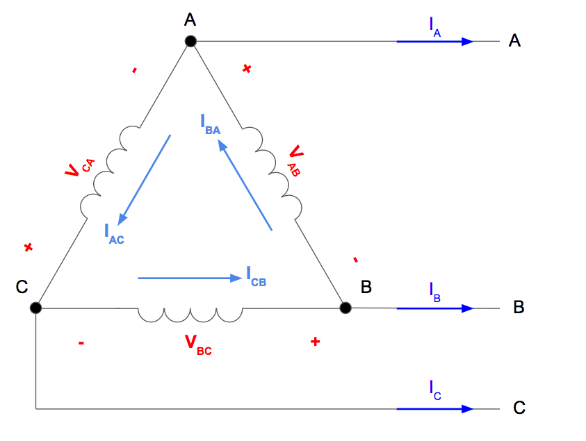
Let’s start by looking at the standard three phase delta connection.
Below is a diagram of three single phase transformers connected in delta to form a three phase delta transformer. For the sake of this article let’s assume we are working with a balanced, positive ABC sequence system.
2. Three Phase Delta Transformer Phase Voltages
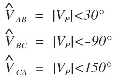
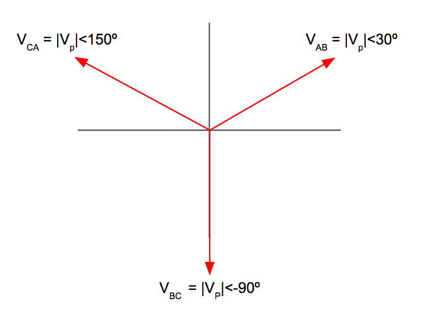
For our phasor diagrams, let’s use a reference of zero degrees for the A phase line to neutral voltage of the system, meaning that the A-phase voltage of the delta, which is equal to the A line voltage of the system, will be at a reference of 30 degrees.
With the chosen reference angle and a balanced, positive sequence system we can determine the delta phase voltages:
Here is the resulting phasor diagram for the delta phase voltages:
3. Three Phase Delta Transformer Phase and Line Current
Next, let’s assign the three phase delta phase and line currents that will occur during maximum power conditions.
Maximum power conditions for a transformer exist when the power factor is unity.
When this is true, the delta phase current will be exactly in phase with the delta phase voltage, and the active power output in watts (P) will be equal to the apparent power volt-amp rating (S) of the transformer:

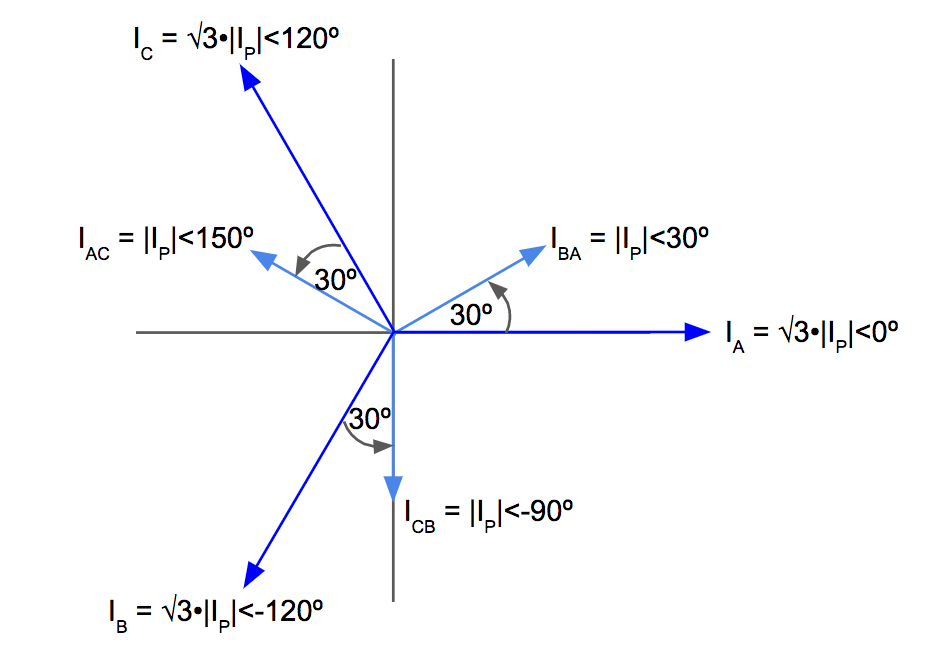
Since we know that each delta phase current is now in phase with each delta phase voltage, the phase currents will have the same angle as their respective phase voltage. This lets us determine the complex value of each delta phase current.
From there, we can determine each system line current since by definition they are larger by a factor of √3 and lag by 30º compared to their respective delta phase current:

Notice each phase current has the same angle as the previously determined delta phase voltage since power factor is equal to unity.
Here is the resulting delta phase current and system line current phasor diagram:
4. Three Phase Delta Maximum Power Formulas
If we graph the delta phase current and delta phase voltage on the same phasor diagram we can verify that power factor is unity since the angles are equal for each pair of phase current and phase voltage.
Recall that this is the correct relationship that will result in maximum power output for the delta transformer:
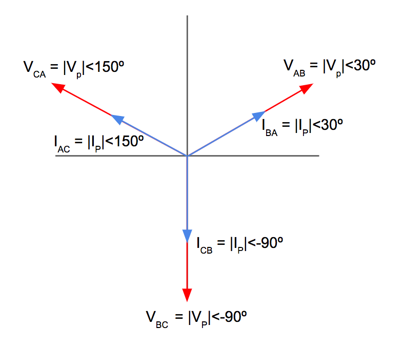
Now, let’s solve for the total three phase power of the delta transformer during these conditions by adding up the power delivered by each of the three windings.
Theta is equal to the difference between the phase voltage angle and the phase current angle. Since these angles are equal, theta is equal to zero for each pair:

The maximum power delivered by a three phase delta transformer is equal to three times the delta phase voltage magnitude times the delta phase current magnitude.
5. Three Phase Delta Sample PE Exam Practice Problem
Example – Determine the maximum power of a three phase transformer if three individual single-phase transformers rated for 150kVA and 4,160V/480V are connected in delta.
Let’s use the previous formula we derived to solve for maximum power.
Note that we can use either the secondary phase voltage with the secondary phase current, or the primary phase voltage with the primary phase current and still get the same answer.
In our calculations we are using the secondary values:
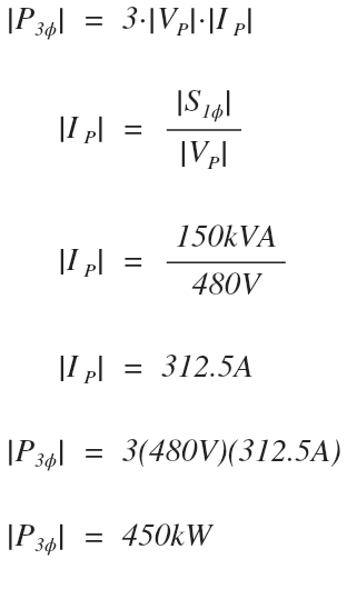
The maximum output power of this transformer configuration is 450kW.
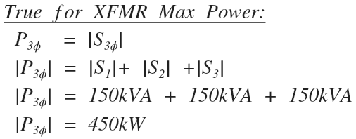
Since the active power output in watts is equals the apparent power rating of a transformer in volt-amps during maximum power conditions, we can check our work by adding up the power ratings of each individual single-phase transformer used to make the three phase transformer:
So far so good, this is the easy stuff.
Now that we are familiar with the maximum power relationships for the three phase delta transformer, let’s look at what happens when one winding is removed and we are left with the open delta transformer connection.
6. Open Delta Transformer Connection Diagram
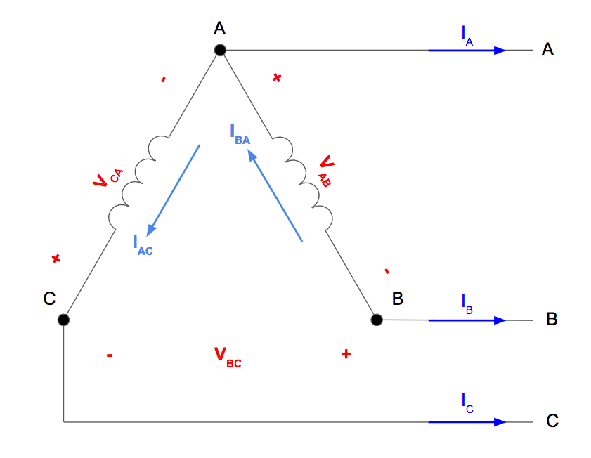
Let’s pretend that while in service, the “B” phase of a standard three phase delta transformer failed, this is the winding located between the B and C connection. Let’s also pretend that the other windings were left intact and unaffected by the failure.
This results in an open delta transformer configuration that looks like this:
7. Open Delta Transformer Phase Voltages
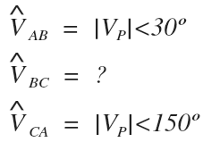
Just as before, we will use a reference of zero degrees for the A phase line to neutral voltage of the system, meaning that the A-phase voltage of the delta, which is equal to the A line voltage of the system, will be at a reference of 30º.
So far, nothing has changed for the delta A-phase and C-phase voltage, but we are not so sure about the delta B phase voltage just yet:
Let’s pretend we can connect a voltage meter across the B to C connection where the missing winding and measure what the new open delta voltage is across B to C.
We will use a positive polarity reference at B and a negative polarity reference at C, just like what the line would see prior to the winding failure.
Looking at this as a KVL loop, we can see that we have two voltages in series which we can add by summing the values.
Starting from the B to C connection we have negative A-phase delta voltage followed by the negative C-phase delta voltage from the A to C connection.
Let’s use a delta phase voltage magnitude of 1 so that we can plug these values into our calculator and see if the magnitude and angle increases or decrease in value:
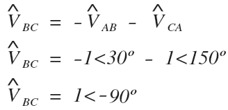
The magnitude of the voltage across the missing winding has neither increased or decreased in value, it is equal to the previous magnitude of the same balanced phase voltage.
The angle of the voltage across the missing winding has also neither increased or decreased in value. It is still equal to the angle of the voltage that was there prior to the winding failure.
The surprising finding is that the connected three phase system sees no difference in the supply voltage with the missing winding!
The open delta phase voltages are identical to the three phase delta voltages prior to the winding being removed:

The resulting open delta phase voltage phasor diagram is identical to the previous delta phase voltage phasor diagram with all three windings in service:

8. Open Delta Transformer Line Current
Now let’s inspect the open delta phase and line current. This is where it gets a little bit more difficult.
We will start with the line current.
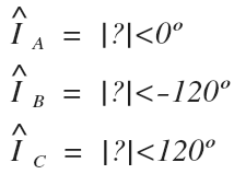
First, recognize that there is no change in the system line voltage since the open delta phase voltage is identical to the three phase delta phase voltages. The result of this is that the angles of each system line current will be the same as before.
The magnitudes of the system line currents will still be balanced and equal, but will be different in value since the previous KCL formulas for a three phase delta no longer apply with the missing winding:
9. Open Delta Transformer Phase Current
Now let’s look at the open delta phase current.
Recognize that when we look at each of the single-phase transformers individually, even though the B phase transformer is no longer connected, it does not affect the full load amps of each of the two remaining single phase transformers that make up the two remaining windings of the open delta transformer.
The result is that each phase current in the two remaining open delta windings will have the same magnitude as before.
However, since the KCL relationship has been changed by removing a connection between the B an C phase, the angles will be different than before:

10. Open Delta KCL Relationship For Phase and Line Current
Let’s look at the open delta connection again and see if we can set up KCL formulas to relate the open delta phase and line currents:

Let’s start with the C-line and C-phase current since they have the easiest relationship:
Looking at the open delta digram, the C line current is now equal to the C phase current for the open delta connection since the B winding is missing.
Since we know the magnitude of the C line current, and the angle of the C phase current, we can determine the complex value for both:
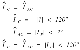
The C-line current and the C-phase current both have a magnitude equal to the previous phase current magnitude with an angle of 120 degrees.
Next, let’s move on to the B line and phase current since they have the next easiest relationship:
Looking at the open delta diagram, the B-phase current is equal to the negative B-line current since they are flowing in opposite directions. This is the same as multiplying the complex value by negative one to change the direction.
Multiplying a vector by negative one does not change the magnitude, it only rotates the vector by positive or negative 180 degrees.
Since the B-phase current equals the negative B-line current, we know that their magnitudes are equal.
We already know the B-phase current magnitude and the B-line current angle.
We can find the missing B-phase angle by rotating it 180 degrees and solving for the complex values for both:
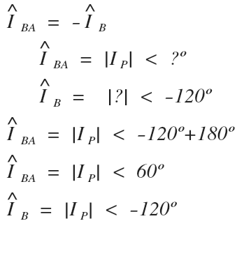
The B phase and line current are equal in magnitude, and 180 degrees apart.
Last, let’s move on to the A line current since it requires summing up the two previous open delta phase currents that we just solved for.
Looking at the open delta diagram and using KCL node equations, the A-line current is now equal to B-phase current minus the C-phase current.
We will use a phase current magnitude of 1 so that we can plug these values into our calculator and solve to see if the magnitude or angle increases or decreases with this new KCL relationship:
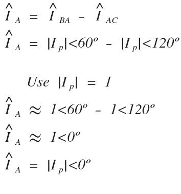
The A-line current has a magnitude equal to the phase current magnitude with an angle of 0º degrees.
We can check our work by verifying that we already determined that the A-line current had an angle of 0º in our previous steps.
11. Open Delta Phase and Line Current Phasor Diagram
The open delta phase and line currents we determined are:

Let’s draw all three line currents and both phase currents on the same phasor diagram.
Note that the C-line current and the C-phase current are equal and share the same vector:
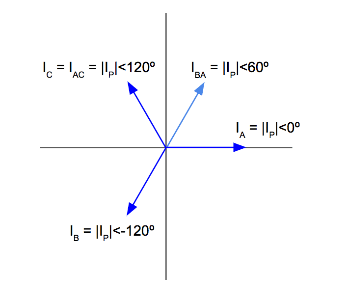
Last step, it’s time to finally understand where the formula for open delta power comes from.
12. Open Delta Maximum Power Formula
Even though the open delta can still serve a three phase load provided it has enough capacity, to find the maximum power we will only be looking at the two windings that remain.
Let’s draw a phasor diagram that shows both pairs of the remaining phase values, the A-phase voltage and current, and the C-phase voltage and current.
Note that we are not using line values because we want to find the complex sum of both remaining individual single phase transformers that each make up the two remaining phase windings of the open delta transformer:
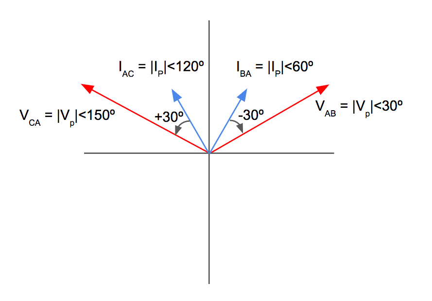
Even though the open delta configured transformer is operating at maximum power conditions the phase currents and phase voltages are no longer perfectly in phase and have a displacement between them that is no longer equal to zero degrees.
Let’s take the complex sum of both remaining windings to determine the total maximum power that the open delta transformer can deliver:
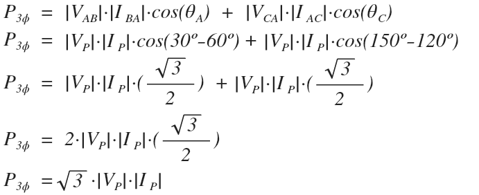
The maximum three phase power that the open delta configured transformer can deliver is √3 times the phase voltage magnitude times the phase current magnitude.
13. Open Delta Max Power vs Standard 3ø Delta Max Power
Intuitively we know that an open delta transformer cannot supply as much power as a standard three phase delta since one of the windings is missing.
Since we already derived the formulas for both maximum open delta power and maximum standard delta power, let’s see if we can determine the percent difference.
This only works we are comparing an open delta three phase transformer with the same single phase transformer ratings. For example, if a three phase delta transformer loses one of its windings, or, if the same rated single phase transformers are used to make both a three phase delta transformer and an open delta transformer.
In both cases, the magnitudes of the phase voltage and phase current will be equal between the two types of delta transfomers:
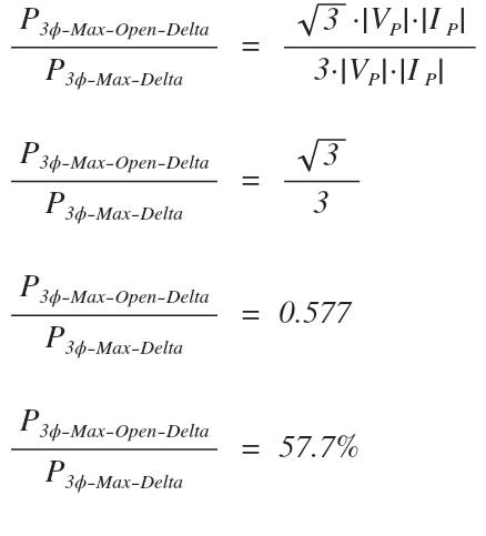
An open delta transformer can only supply 57.7% of the power that a three phase delta transformer with equal single phase transformer ratings can deliver.
This is quite a large decrease in power when only losing a third of the overall three phase transformer windings.
14. Three Open Delta Sample Exam Practice Problem Examples:
Ex 1. Three single phase transformers rated for 10MVA 13.8kV/4,160V are connected in delta to form a three phase transformer. Determine the maximum power that this three phase transformer can deliver.
We can solve this two ways.
The first method:
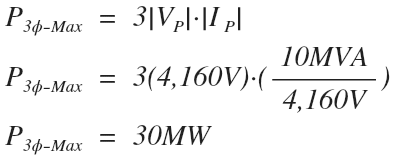
The second method:
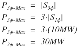
Note that both methods yield the same maximum value of 30MW of power delivery by the three phase delta transformer.
The first method we used the secondary voltage and the secondary FLA for the phase voltage and phase current magnitudes.
We could have just as easily used the primary voltage and the primary FLA instead (try it and verify the results).
Ex 2. Two single-phase transformers rated for 10MVA 13.8kV/4,160V are connected in open delta to form a three phase transformer. Determine the maximum power that this three phase transformer can deliver.
Time to use the max power formula for an open delta transformer:
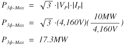
Notice that the three phase open delta transformer with two windings will only deliver 17.3MW compared to the previous 30MW with three windings.
The trick here is that with open delta, we can’t just add the power ratings of both windings (10MW + 10MW ≠ 17.3MW).
Again we used the secondary voltage and the secondary FLA for the phase voltage and phase current magnitudes but we could have just as easily used the primary voltage and primary FLA values instead to get the same results (try it and verify).
Ex 3. Three single phase transformers rated for 10MVA 13.8kV/4,160V are connected in delta to form a three phase transformer. While in operation, one winding fails without damaging the other two. The transformer continues to provide power in an open delta configuration. Determine the percentage of power that the open delta configuration is able to supply compared to when all three windings were in service.
We can solve this two different ways.
Since we already did the math in the previous two examples, let’s use the previous values we calculated to find the percentage of power that the open delta can supply compared to when all three windings were in service.
We can do this by dividing the max power we determined for the open delta transformer by the max power we determined for the delta transformer.
The first method:
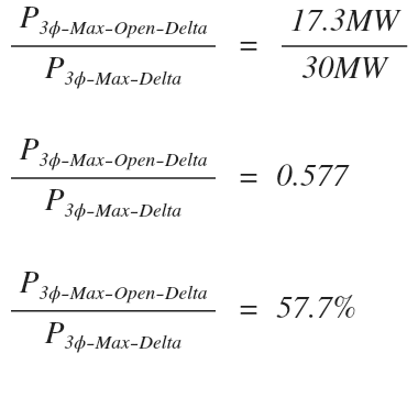
The 17.3MW of power that the open delta can deliver is only 57.7% of the previous 30MW of power that the transformer was able to deliver before the winding failure.
The second way to calculate this is to compare the formulas for open delta maximum power to standard delta maximum power.
Since the phase voltage magnitudes and phase current magnitudes are equal, they will cancel.
The second method:
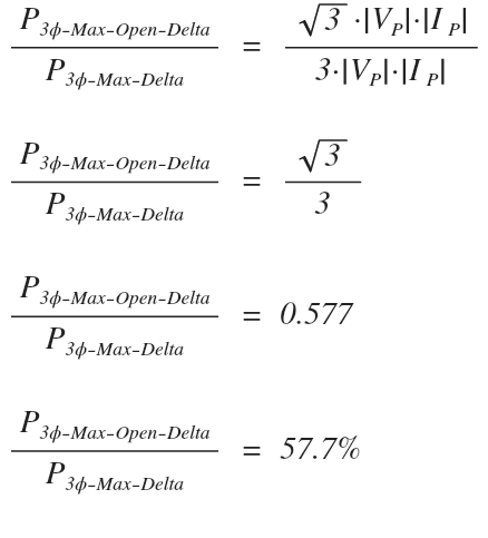
Notice that we still get the same answer without having to know the actual values of the phase voltage or phase current magnitudes!
15. Thoughts? Questions? Comment Down Below.
Have you ever come across a real open delta during your career in the industry?
Is this the first time you’ve seen a full-length explanation on the open delta configuration?
Have any lingering questions after working your way to the bottom of this article?
Join the discussion by leaving your comment down below.
We respond to all comments in a timely manner.


Great article.
You are right on. There are hardly any articles online that cover this topic.
I appreciate your efforts and will share this information with my coworkers.
Glad you enjoyed it Mark.
Hey Zach,
Can you create an example like that, but for an open delta with different size Transformers. Say the Power Transformer is a 15kVA and the lighter is 25kVA. What would be the maximum 3 phase power output for that configuration? Thanks!
Hi, If we want to protect it using Differential Protection, what is the vector rotation? Can we achieve the balance current from what is going in to what is going out?
In Section 7 of the OD analysis the calculation says “Vbc=1<90" and I believe it should match your graphic which is at -90 and you are just missing the minus 90 degrees for the angle.
Thanks Doug! This has been updated.
An open Δ bank delivers a balanced three-phase load of 60 KVA at 460 volts. A) what current flows in
the secondary of each transformer?
Section 3. IAC phase current angle should be +150?
Thanks Harith, this has been corrected.
Thanks Zach
I really enjoyed the explanation of open delta transformers that you present in this article using circuit analysis. My other references only provide a brief description and equation.
This really helped me visualize and understand the concept of Open delta systems. It was really frustrating to find any easy simple explanations on this topic!
Thanks Zach!
This is a good article that explains a concept otherwise a little hard to comprehend.
This was a good article. The phasor diagrams provide great visuals to remember. Thank you Zach
Great explanation of a difficult topic. I will definitely be bringing a printout of this article into the exam.
This is a great article. I don’t think I’ve come across a breakdown as you have done with such a description as to what is needed to be done to calculate Max Power for an open delta. Seeing each step and explanation why you are doing something is beyond what you can find in any resource! Thanks!
Zach, thank you very much , such an amazing article, i never found such explanation anywhere else, you made it very easy to derive .
This was a very helpful article, as there are not many reference materials that deal with open-delta transformer configuration.
Thanks Zach,
This was another one of those topics that I was completely unfamiliar with before I began studying for the PE Exam. Zach did a really nice job explaining the topic in this article, and he also did a great job covering in the live class.
Thanks for the kind words Justin! As always, glad you enjoyed it.
what a great article and explanation with drawings, step by step, not like reading a book and give you beginning and ending, and nothing in between
Great article with detailed overview. I could never find a good article on open delta connections, and even less remember the significance of them. This cleared it up immediately. Thanks Zach!! To all aspiring PE takers…this course beats all others!!!
Thanks Alex, glad you enjoyed.
Great explanation!
Excellent Article. Thank you very much Zach!
You are most welcome Frederico.
Great article with detailed overview. Zach really knows how to explain each topic.
Thanks for the kind words Jon, best of luck on the April PE exam.
I was always afraid of the open transformer type question. Thanks for breaking it down and making it understandable
Thanks Phillip. Nothing to be afraid of once you can see where every value comes from.
very well explained ! thank you.
Great article Zach! Super helpful and will reference for the test (and any future applications)
I must say when it come to understanding the Open Delta Transformer it was difficult, but after going this article I feel a lot better regarding this topic. This article was very helpful.
I love this article. This is a good example of a topic such a transformers where you might work out many practice exam problems but never come across something like this. This is something you might expect the test makers to sneak in so this is good stuff and I love the example problems at the end.
This is a tough topic to comprehend. Thank you Zach for your clear instructions.
Zach
This is another article that does a simple outline of the basics to help understand transformers vs trying to over complicate the subject like some other discussions.
Great in-depth explanation!
Great explanation! Thanks Zach!
Steps by step explanation makes it very easy to understand. Thank you Zach!
Great way of simplifying a difficult concept! You have a rare gift to simplify concepts the way you do!
Great work! Thank you!
What happens if PF is not unity?
I have a question. We run an open delta in our plant. We have 480 when checking across phases but 480 on 2 legs and 0 on the 3rd going to ground. What causes this?
You should now show how to calculate fault current values for the open delta connection, something that customers needed for sizing their protective equipment.
This open delta transformer article was extremely helpful to me since I struggle with this topic as well and fumble through it only to derive the wrong answer. This is a well designed article and would recommend that others would read through it to gain a better understanding of this type of transformer configuration and of course pass the PE exam. Thank you for a job well done Zach!
THANK YOU FOR THIS! I’ve printed this out and added it to my references for the exam. I’ve also sent the link to this to some of my colleagues! Thank you again
Open delta TX was one of those things that i used to think I was knowledgeable about but then reading Zach’s article I found out that i was missing some of the basics behind this application. Now i can easily draw the circuit and tackle any open Delta TX problem without looking to my resources. Once you get to understand the fundamentals behind is way more easier to solve any question. Highly recommend Zach’s materials. Thank you Zach!
ahhhh Open Delta. This little guide has helped me understand the open delta configuration. This real life possible scenario weather by accident or on purpose has helped me understand the fundamentals as well on Voltages in Delta.
Great article. I was searching all over the internet and this article is definitely the best way to explain the open delta connection. It helped me to easily understand how the open delta connection works and where it is used. Thanks Zach.
Before seeing this article I didn’t understand how to solve for open delta. After reading the explanation Zach presented, it made it much easier to solve.
Great Article, open delta is an important topic. I learned delta voltage and current phasor diagram both in normal condition and in open condition. Solved couple of problems from different practice exams using this free article as well.
My understanding on the Delta transformers went from Scale 1-10, It went from 3 to 9
Excellent article. Open Delta is a concept that I didn’t fully understand. Working for the power industry, this was always viewed as a temporary solution. Seeing it explained helped my understanding.
This article is really helpful. I feel like I can finally understand, where does the 57.7% came from. And that is huge.
Thanks Zach
There was an open delta problem on Oct 2018 exam. I’m sure I got it wrong, this article is helpful reference.
This was an interesting module. Even though I HATE Open Deltas, I can now say I understand them a lot more. Really glad i found your site.
This was a great example of how Open Deltas work similarly to regular delta connection in terms of power. They are slightly different but with these equations and examples it’s easy to understand. Thanks Zach!
Can’t get any more detailed with the step by step explanation on with how the open delta transformer connections work. I’ve never seen a problem regarding an open delta transformer. After reading this article a few times and printing it out, I’m confident I can solve any type of PE exam problem regarding this topic.
Breaking things out using phasors helps with a visual and really makes the difficult concepts easy to understand. Good article!
Great Article. I have experienced this a few times in my field and I never fully understood how it worked. This article clearly outlines the multiple formulas to use. Thanks!
The article is great. I always struggled with open delta, and this article and the course helped me understand more this subject. I highly recommend the course.
Zach, Will you please do a walk-through of calculating available fault current on an open-delta bank? I appreciate your work!
Awesome, thanks.
Going to feed a VFD from an open delta and have been wondering about the phase angles. This completed my picture…
Hi Zach,
Thanks for this great in depth article. I wanted to ask if you could show the calculations for 3VO if
a) one of the phases is lost under fault
b) a fuse is blown (no fault)
What would be the maximum voltage reached if 1 ph is lost, 2 phases are lost; considering 115V supply to the relay.
Thanks
Ed
Zach,
This is a great reference, thankyou! Can you just explain why the max power you are calculating is in MW and not MVA?
Thanks again
Another topic that is tricky but once combing through all your material and having this really helped me so much! Very good article, lots of very detailed explanations that go beyond other resources.
Thanks for shedding light on this obscure topic
Thanks for taking the time to work thru this. Great article that explains the topic to point. Thanks Zach!!
Great article. Phasor diagrams were never my topic of interest but this article made me understand it better even for open delta connections.
Hi Zach,
I don’t see open delta transformer. Having this information helps me to understand how this works. Thank you for having this i article available for us.
Great derivation! Helps so much to understand.
This article makes the open delta connection incredibly easy. Almost TOO easy. I can’t believe I struggled to understand this for so long. Great article.
This by far the best article I have read on this topic. Great read, nice work Zach
Note the National Electric Code mandanates that the secondary 270 Volt is the Bn phase that forces the secondary voltages to be Note the arrow head is the first letter of the subscript
Vac = 240(wt + 0 Degrees)
Vba = 240(wt + 120 Degrees)
Vcb = 240(wt + 240 Degrees)
Note Using electron current flow the voltage and currant are in the same general direction
Can you correct your nomenclature ?
There are many open delta services in Houston the power co. Likes them for small 3 phase loads because it saves a transformer and helps correct the lagging power factor.
Another thing the transformer for the single phase and 3 phase service Vac is large but the second transformer Vcb is usually 50% smaller and forcing the currant to lead the voltage.
The open load voltage Vab=240(wt + 300 Degrees) and is the reverse direction of the close delta Vba
I would like to see a simplified example problem with one motor load 240V , 3ph. about 6,000 watts and power factor of 86.6% and a single phase load on transformer Vac of an additional 1 kW . Calculate the currant and power for each transformer. Vac and Vcb.
Could you possibly cover the advantages of open delta connection and its use in PTs for ground fault protection? I have read somewhere that during a ground fault where zero sequence current cannot flow through the open leg, the zero sequence voltage rises sensing the relay for overvotage condition, closing the contact of the relay installed in the trip circuit of the circuit breakers in substaion applications. Please correct this description if you find anything contrary to the above description.
Hii,
I would like to ask a question here. Is there any condition in a three phase supply such that a bulb on one phase is brighter, a bulb on another phase is dim and a bulb on 3rd phase is in normal brightness.. as a result of an open delta transformer???
Zach,
Section 12. Open Delta Maximum Power Formula. Theta A and Theta B angles were swapped. It will give you the same results but to maintain consist with the derived formula I would recommend to change these values.
Other than that, great explanation. I just ran into a similar problem where we lost one single phase transformer and had to connect them open delta.
What would happen if you replace 1 out of the 3 single phase transformer with a transformer that has same ratings except the percent impedance? Is this explain somewhere in the demand course? We were tempted to do this since we did not have a single phase transformer with the same impedance value.
Cheers!
Edgar
What is the relationship between phase and line voltages in an open Delta?
I get that in a Delta Vline=Vphase
What about open delta?
Thank you very much for your detailed article, I have not seen a clearer explanation of an open delta system.
I do have a request, do you think you can also provide the fault analysis calculations as well? What is the sequence network for a A to B fault on an open delta, or C to B, or A to C? Thank you.
Important Article for Power Engineers
A lot of times in DELTA systems a two-bank voltage regulator is used instead of three banks. How would this relationship be for an open delta voltage regulator? Would the capacity of two bank regulator be also reduced by 0.57 of the capacity of three banks?
I am an Electrical Inspector. I did an inspection on a open delta system. 750 kcml is the largest ungrounded conductor. As per 250.66 you need a 3/0 minimum size main grounding conductor. The engineer has sized a #6. I have been in the Mechanical trade 40 years and have been doing Electrical 5 years. Is there something I am not considering in the sizing of the main grounding condictor?