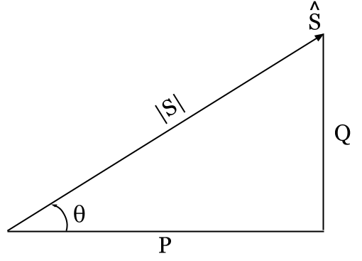
Power Triangle for a Single-phase Circuit
What’s in this Article? Click below to jump to any section:
- Power Factor Basics Video Example With Phasor Diagrams, Power Triangles, and Unity Power Factor Explained
- Calculating the Power Factor (PF) of a Single-phase Circuit Using Voltage (V) and Current (I)
- Calculating the Power Factor (PF) of a Single-phase Circuit Using a Power Triangle from Complex Power (S)
- Unity Power Factor (PF) – Purely Resistive (R) Circuit Phasor Diagram
- Unity Power Factor (PF) – Purely Resistive (R) Circuit Power Triangle
- The Power Angle of the Circuit (θ) is Really the Total Connected Impedance Angle (θZ)
- Questions? Thoughts? Leave a Comment Below!
Related Power Factor Articles:
Electrical PE Review – Leading and Lagging Cheat Sheet! Printable Reference
1. Power Factor Basics Video Example With Phasor Diagrams, Power Triangles, and Unity Power Factor Explained
Watch the video above to learn the basics of power factor for a single-phase equivalent circuit, including phasor diagram and power triangle relationships.
In the first example we go over an example using 120V for the single-phase applied voltage and total connected impedance of Z = 5 + j3 Ω and show every way that power factor can be calculated.
In the second example we keep the voltage the same but use a total connected impedance of Z = 5.83 Ω to explain unity power factor (PF = 1).
2. Calculating the Power Factor (PF) of a Single-phase Circuit Using Voltage (V) and Current (I)
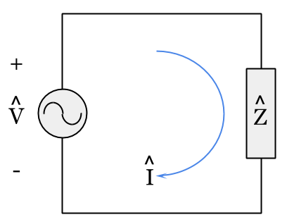
Single-phase Circuit Diagram
Using Ohm’s law, we can calculate the total complex current (I) drawn by the total circuit impedance (Z) from the applied voltage (V) in the single-phase circuit diagram shown above:

Next, we can draw a phasor diagram using the current (I) and voltage (V):
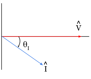
Phasor Diagram for a Single-phase Circuit
Looking at the phasor diagram above, our first formula for calculating power factor (PF) is the cosine of the difference between the voltage phase angle (θV) and the current phase angle (θI):

Notice in the phasor diagram above, the voltage phasor is directly on the horizontal x-axis. We are using a reference angle of zero degrees for the voltage phase angle (θV = 0).
If you use a different reference angle when you calculate current (I) using Ohm’s law, you’ll end up with a different current phase angle (θI). Even though both the voltage phase angle (θV) and the current phase angle (θI) will be different, when you calculate power factor (PF) you will still arrive at the same answer since the difference between the two angles (θV – θI) will still be the same.
Try verifying this for your self by repeating the exercise in the video above using any reference angle other than zero degrees for the applied voltage (V).
For example: try using an angle of 30 degrees for the voltage phase angle (θV = 30º) to calculate the current (I). Then calculate the power factor (PF) using all of the formulas and steps shown in the video.
3. Calculating the Power Factor (PF) of a Single-phase Circuit Using a Power Triangle from Complex Power (S)
The next few formulas for calculating power factor (PF) requires us to know the complex power (S) drawn by the circuit. We can calculate the complex power (S) by taking the product of the applied voltage (V) and the conjugate (*) of the current (I) drawn by the circuit:

Expressed in polar form, this formula results in the apparent power |S| and power angle (θ):

Expressed in rectangular form, this formula results in the real power (P) and reactive power (Q):

We can use the polar and rectangular expressions of complex power (S) to draw a completed power triangle for the single-phase circuit:
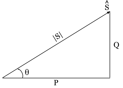
Power Triangle for a Single-phase Circuit
We can now calculate the power factor (PF) of the circuit as (1) the cosine of the power angle (θ) or (2) the ratio of the real power (P) to the apparent power |S|:
4. Unity Power Factor (PF) – Purely Resistive (R) Circuit Phasor Diagram
When a circuit is completely resistive (R), the complex impedance has a zero reactance (X = 0) value:

Using Ohm’s law again to calculate the complex current (I) drawn by the circuit, we find that when the complex impedance has a zero reactance (X = 0) value, the current (I) will have the same phase angle as the applied voltage (V).
The result of this is that the current (I) and voltage (V) are in phase with each other and the circuit has a power factor of unity (PF = 1):
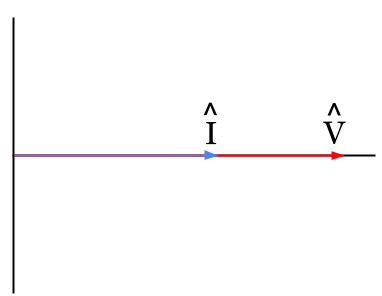
Unity Power Factor Phasor Diagram
There are several special conditions of a unity power factor (PF = 1) circuit.
The first, as we have already seen, is that the complex impedance is purely resistive (Z = R + j0 = R). The second, looking at the phasor diagram above is that the voltage phase angle (θV) the current phase angle (θI) are equal:

5. Unity Power Factor (PF) – Purely Resistive (R) Circuit Power Triangle
If we calculate the complex power (S) of a unity power factor circuit using the applied voltage (V) and the conjugate (*) of the current (I) to draw a power triangle, you’ll notice that the power triangle no longer looks like a triangle and instead is a straight horizontal line:

Unity Power Factor Power Triangle
This is because the three remaining special conditions of a unity power factor (PF = 1) circuit are that (1) the apparent power |S| and real power (P) of the circuit are equal, (2) there is no reactive power (Q), and (3) the power angle (θ) of the circuit is zero degrees:
6. The Power Angle of the Circuit (θ) is Really the Total Connected Impedance Angle (θZ)
The final important realization of power factor (PF) basics, is that the power angle (θ) of the circuit is actually equal to the angle of the total connected impedance (θZ) of the circuit. To explain, let’s look at the formula for complex power (S) as the product of the applied voltage (V) and the conjugate (*) of the current (I) drawn by the circuit:

Next, let’s expand the voltage (V) and current (I) into their magnitudes and phase angles:

Watch out for the conjugate (*). Normally phase angles sum (+) when multiplying polar numbers, however, due to the conjugate (*) the polarity of the current phase angle (θI) has been reversed.
Looking at the above, we can define the power angle (θ) as the difference (-) between the voltage phase angle (θV) and the current phase angle (θI):

Next, let’s look at the relationship between the total connected impedance (Z) of the circuit, the applied voltage (V) of the circuit, and the total current (I) drawn by the circuit using Ohm’s law:

Let’s re-write Ohm’s law to solve for impedance (Z) and then expand the voltage (V) and current (I) into their magnitudes and phase angles just like we did before:

Notice that the angle of the total connected impedance (θZ) is also equal to the difference (-) between the voltage phase angle (θV) and the current phase angle (θI), just as we found before with the power angle (θ):

This is because, as we described above, the angle of the total connected impedance (θZ) is actually the power angle (θ) of the circuit:

This is where the power factor of a circuit comes from.
7. Questions? Thoughts? Leave a Comment Below!
Would you more example videos and work through practice problems on Power Factor and Power Factor Correction?
Head over to Chapter 8.3 Power Factor Correction and Voltage Support located in the Online Review Course for the Electrical Power PE Exam.
Do you have any more questions on the Power Factor, or thoughts to share on the subject?
Leave a comment below and join the discussion!
Related Power Factor Articles:
Electrical PE Review – Leading and Lagging Cheat Sheet! Printable Reference



Why would you change ohms law to impedance? Should use resistance and cause a lot less confusion for people not electrically inclined. Also, how is it possible for you to change the reference angle of the voltage and still get the same answer? Thats not how math works. If one tying in an equation changes, your answer should be different. Youre saying its the same. That isnt possible. Either the equation is wrong or the math was done incorrectly.
Hi Ashley,
Thanks for your comment. These articles are intended for electrical engineers that are preparing for the Power PE Exam, and made for individuals that are already familiar with the basics of electrical engineering and complex numbers like impedance (Z).
Ohm’s law calculates the voltage drop (V) due to the product of current (I) flowing through an impedance (Z). It is quite common to see a more simplified and derived version of Ohm’s law that does not use complex numbers with resistance (R) in place of impedance (Z) for 100% resistive circuits when there is no reactance (X) present.
Since this is an article about power factor due to the presence of reactance (X) in a circuit, the use of impedance (Z) is required instead of just resistance (R).
When the impedance (Z), or load on a circuit is constant, then changing the voltage reference angle will only result in a different phase angle for current, it will not change the current magnitude (try it in your calcualtor).
We use phasor diagrams as a tool to understand circuits, but it is best to think of them as a snap shot, or picture, of a moving diagram. While phasor diagrams are stationary when we draw them on paper, in real life both the voltage and current value are changing 60 times a second for a 60-hertz system.
Typically, it’s most helpful to use a value of zero degrees for the phase voltage reference angle so that the resulting current angle can be immediately used to determine the power angle of the circuit (θ).
When you change the voltage reference angle, the resulting current phase angle will also change in value by the same amount. Since both are changing by the same amount, the power angle of the circuit (θ) and the power factor remains unchanged.
Very nice explanation and very useful